Mechanical installation, Support structure design, Section 2 – Daktronics KE-1010-7.6-RG User Manual
Page 13: Mechanical installation -1, Support structure design -1, 1 support structure design
Section 2:
Mechanical Installation
Note: Daktronics engineering staff must approve any changes made to the displays. If any
modifications are made, detailed drawings of the changes must be submitted to Daktronics
for evaluation and approval or the warranty may be void.
2.1 Support Structure Design
Reference Drawing:
Shop Drawings ......................................................... Refer to Appendix A
Support structure design depends on mounting methods, display size and weight.
The structure design is critical and should be done only by a qualified individual. It
is the customer’s responsibility to ensure that the structure and the connectors are
adequate. Refer to the Shop Drawings for dimensions and mounting clip locations.
Daktronics is not responsible for the installations or the structural integrity of
support structures installed by others.
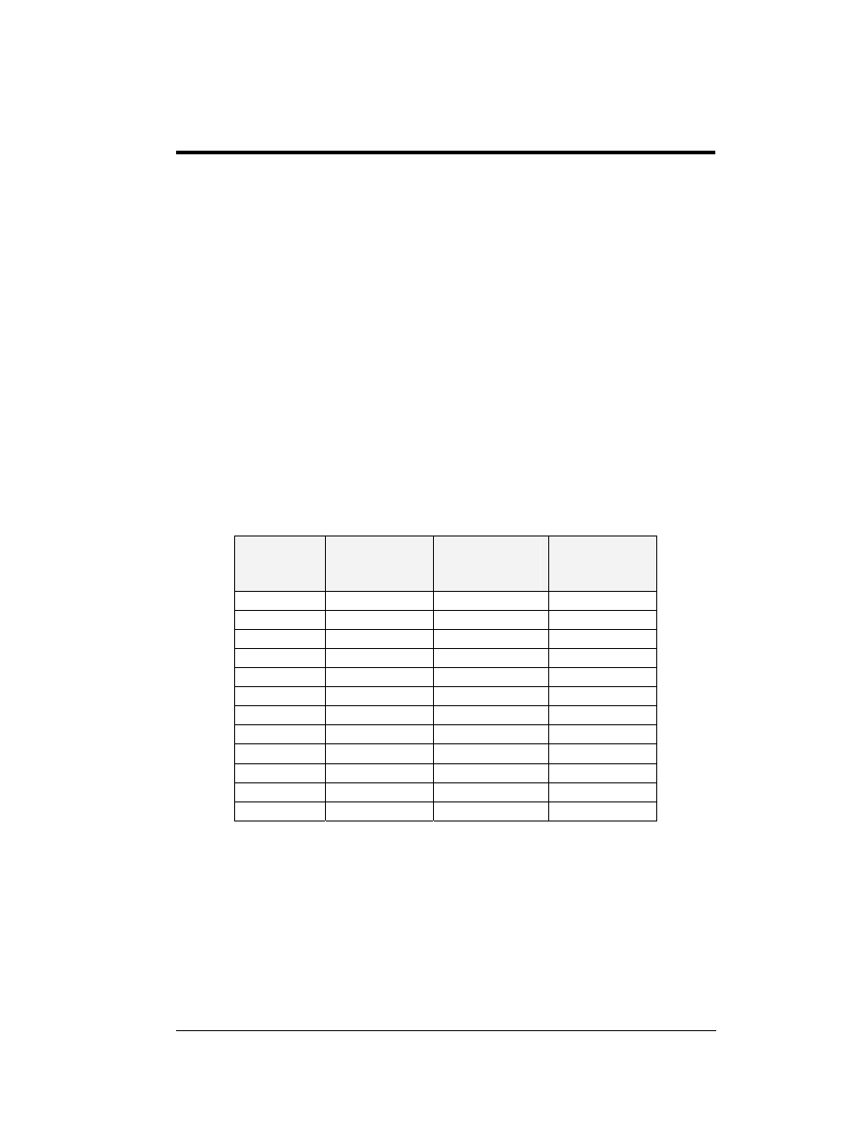
The mechanical specifications of each model are as follows:
Display
Size
Approximate
Display
Height
Approximate
Display
Length
Approximate
Weight (lbs)
16x200
9 ¾ ”
5’ ¼”
35
16x240
9 ¾”
6’ ¼”
40
16x320
9 ¾”
8’ ¼”
50
16x400
9 ¾”
10’ ¼”
60
24x200
12 7/8”
5’ ¼”
45
24x240
12 7/8”
6’ ¼”
50
24x320
12 7/8”
8’ ¼”
70
24x400
12 7/8”
10’ ¼”
80
2-16x200
1’ 5”
5’ ¼”
45
2-16x240
1’ 5”
6’ ¼”
55
2-16x320
1’ 5”
8’ ¼”
75
2-16x400
1’ 5”
10’ ¼”
95
Attaching or hanging anything from the display will render the warranty null
and void.
Mechanical Installation
2-1