Daktronics DF-1050/1051/1052/1053 User Manual
Page 31
Maintenance and
Troubleshooting
4-3
Segmentation and Digit Designation
Reference Drawings:
Segmentation, 7 Segment Bar Digit............................... Drawing A-38532
Electrical Specification Drawings ............................. Refer to Appendix A
In each digit, certain LEDs always go on and off together. These groupings of LEDs
are referred to as segments. Drawing A-38532 illustrates digit segmentation and
details which connector pin is wired to each digit segment along with the wiring
color code used throughout the display.
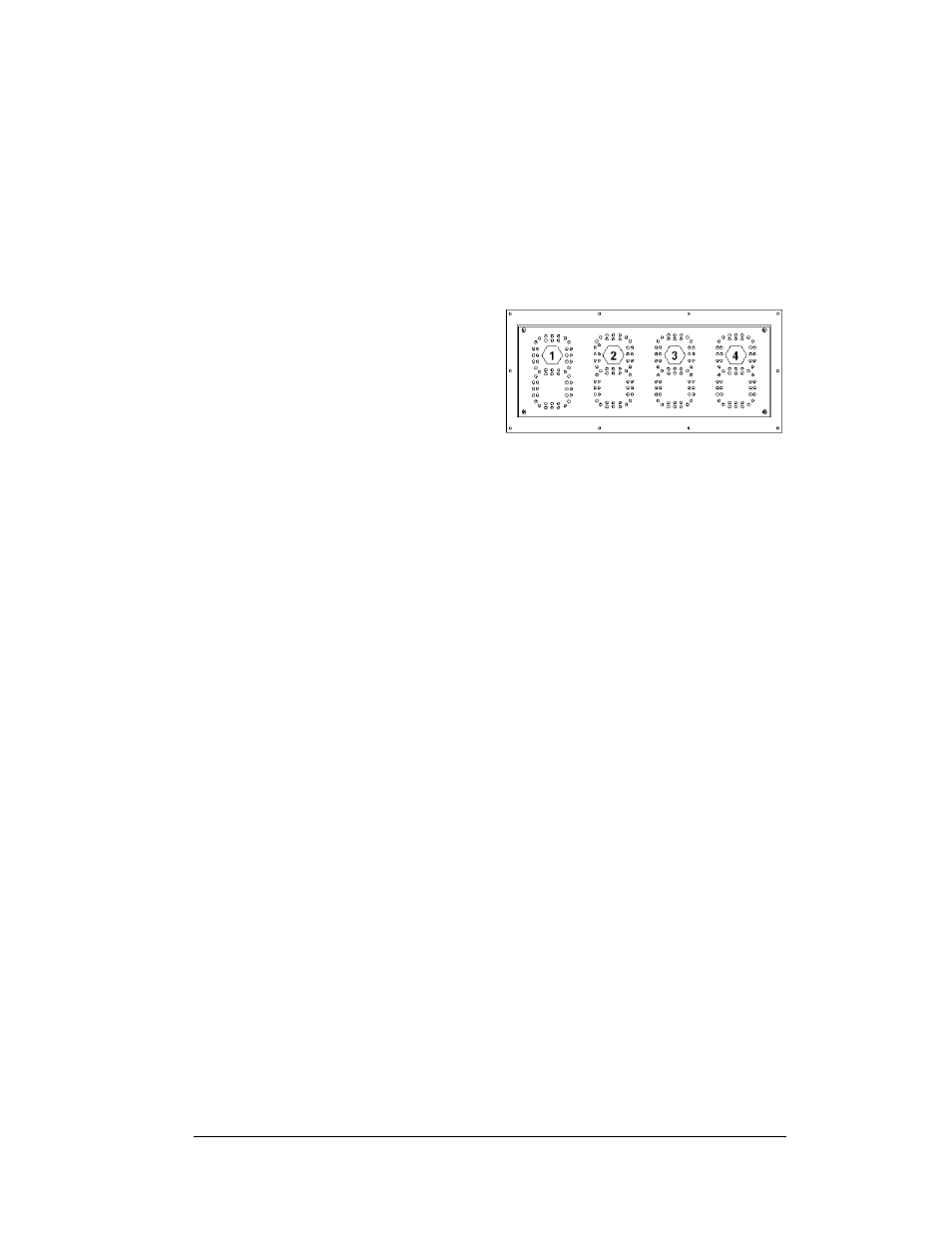
The Electrical Specifications
Drawings for each model specify
the driver connectors controlling
the digits. Numbers shown in
hexagons in the upper half of each
digit, as illustrated in Figure 20,
indicate which connector is wired
to that digit.
LED
Driver
Reference Drawings:
4 Column MASC LED Driver Specifications ................ Drawing A-166216
Enclosed Driver, 4-Col MASC, Wide ........................... Drawing A-191943
Electrical Specification Drawings ............................. Refer to Appendix A
Mechanical Specification Drawings ......................... Refer to Appendix A
Drivers are typically mounted inside the display enclosure and behind the digit face
panel. Refer to the Electrical and Mechanical Specification Drawings for the
location of your driver enclosure. In each driver enclosure there is an LED driver, a
power supply, and termination blocks. Drawing A-191943 illustrates the complete
driver enclosure.
To replace the driver in the display enclosure:
1. Follow the steps in Section 4.2 to gain access to the driver enclosure.
2. Refer to Drawing A-191943 and remove the enclosure cover by loosening
the two side screws and then sliding the cover up to the larger part of the
keyhole opening. Lift the cover off the enclosure.
3. It is helpful to have the cable labeled, noting which was removed from
which connector.
4. Disconnect all connectors from the driver. Release each connector by
squeezing together the locking tabs as you pull the connector free. Note:
When reconnecting, remember that these are keyed connectors and will
attach in one way only. Do not attempt to force the connections.
5. Remove the wing nuts, securing the driver to the inside of the enclosure.
6. Carefully lift the driver from the display and place it on a clean, flat surface.
7. Follow the steps in reverse order to attach a new driver
In the display, the LED driver performs the task of switching digits on and off.
Refer to Drawing A-166216 and Figure 21 for the major functions of a 4-column
driver.
Figure 20: Digit Designation