Conduit, Preparing for power/signal connection, Conduit -5 – Daktronics AF-3160-34-R,A User Manual
Page 23: Preparing for power/signal connection -5, Figure 18: opening the display -5, 4 conduit, 5 preparing for power/signal connection
3.4 Conduit
Reference Drawings:
Shop Drawing, AF-3160-8-32 -34-Mono-Gen2............ Drawing B-178625
Shop Drawing, AF-3160-40/48**-34-Mono-Gen2 ........ Drawing B-178626
Daktronics does not include the conduit. Refer to Drawing B-178625 and Drawing
B-178626 for your display size located in Appendix A for approximate locations for
power and signal conduit. Separate conduit must be used to route:
•
Power
•
Signal IN wires, including phone line
•
Signal OUT wires (if signal is required for another display)
Knockout holes for ½" conduit are located at the bottom right (rear view) of the back
of the display (refer to Drawing B-178625 or B-178626 for your display.
For displays with more than one face, signal and temperature sensor wiring between
displays is normally completed using the quick connect interconnect cable. If not
using the quick connect interconnect cable, the separate signal and temperature
sensor wires can be routed through the same conduit.
3.5 Preparing for Power/Signal Connection
Reference Drawings:
Component Layout Diagrams .................................. Refer to Appendix A
1. Punch or use ½ " (0.875) conduit holes for the desired conduit openings. Be
careful that none of the internal components are damaged. Attach the
conduit.
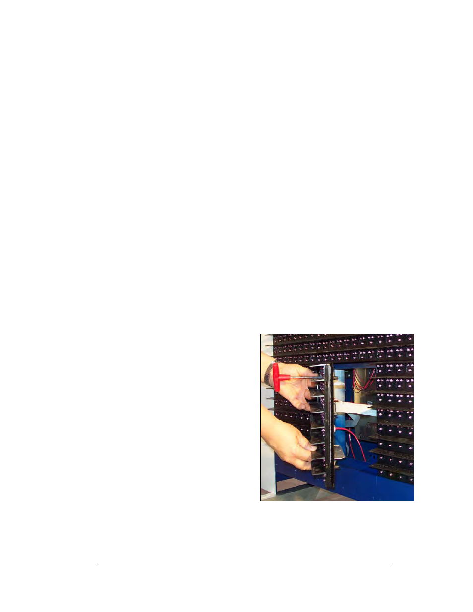
2. Remove the bottom left two
modules (AX01 and AX02) to
expose the power enclosure and
signal panel. Use a
1
/
8
" Allen
wrench to turn the latch access
fasteners one-quarter turn. Turn
the top latch clockwise and the
bottom latch counter-clockwise.
Lift each module away from the
display; reach behind it and
disconnect all power and signal
connections.
Electrical Installation
3-5
3. Locate the controller and power
termination box for these
displays in the Component
Layout Diagram.
4. The controller receives the
incoming signal and relays it to
the individual modules.
5. Route power to the display
through a fused disconnect switch capable of opening all ungrounded power
conductors. Install this disconnect within the line of sight of any personnel
performing maintenance on the display. If the disconnect is located out of
sight of the display, it must be capable of being locked in the open position.
Figure 18: Opening the Display