Rs-422, Figure 22: rs232 signal term panel – Daktronics AF-3165-34-RGB User Manual
Page 24
Electrical Installation
20
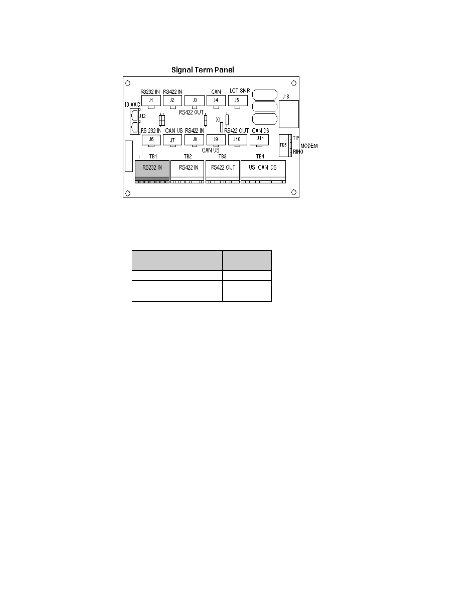
J-Box to Signal Term Panel (A35)
J-box
Wire Color Signal Term
Panel (TB1)
Pin 1 (TX-P)
Black
Pin 1 (RX1)
Pin 2 (RX-P)
Clear or Red
Pin 2 (TX1)
Pin 3 (GND)
Shield
Pin 3 (GND)
RS-422
A display that is controlled using RS-422 requires the use of Signal Converter near the computer. From
the Signal converter cable is run to the Signal termination Panel in the display or to a plug that is
connected to the Quick Connect at the display. The cable from the signal converter to the display must
be routed though conduit. Do not run signal and display power through the same conduit. Refer to
Drawing A-174135 for system layout.
1. If using a quick connect cable, connect from the Signal Converter to J32 on the back of the
display.
2. When connecting directly to the display, terminate one end at Signal converter and the other
end of the wire to the 6-position terminal block in the display labeled “RS422 IN” (A35-
TB2). Drawing B-175387 shows the terminal block wiring.
Figure 22: RS232 Signal Term Panel