Signal summary, Signal summary -2, Figure 17: signal summary – Daktronics AF-3400-133,171,216,260 User Manual
Page 28: 2 signal summary
4.2 Signal
Summary
Reference Drawings:
Schematic, AF-3400-7 (8)X16(A)-***-*-p, 120, 120/240 ........ Drawing B-211433
Schematic, AF-3400-7 (8)X16W/INTC-**-*-P-120/240 1PH.. Drawing B-222321
Refer to Drawing B-211433 and Drawing B-222321 located in Appendix A for
your particular display. The signal routing for the display can be summarized as
follows:
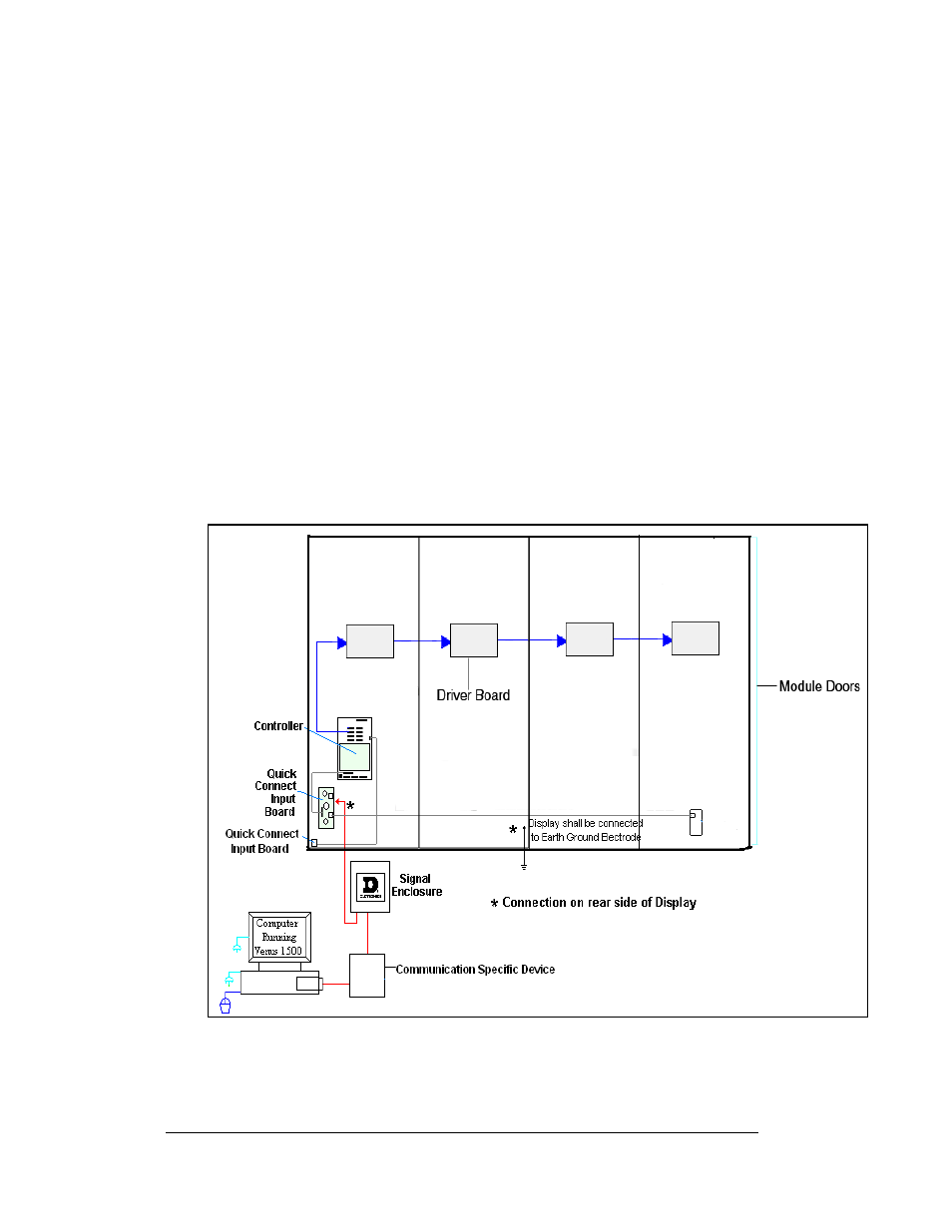
1. Data from the control computer, which runs Venus 1500 software, travels to
the display via one of the seven communication methods.
2. From the controller, the signal then travels over 20-conductor ribbon cables
to the drivers.
3. Data exits at J1 and is relayed to J2 of the next driver board and so on,
traveling down the entire row of modules. The drivers use this display data
to control the individual pixel boards and light the LEDs appropriately.
Refer to Figure 17 for the signal summary in the display
Figure 17: Signal Summary
Maintenance and Troubleshooting
4-2