Dataprobe iBoot-Hub Quick Start User Manual
Quick start guide, Connections
Quick Start Guide
What’s Included
iBoot-Hub Unit
Power Input Cable for North America
Power Outlet Cable for North America
Network Cable
Quick Start Guide
Available Online at
Complete Product Manual
iBoot Setup Utility
iBoot Control Program
Additional Utilities and Programming Tools
To get all the benefits of your iBoot, register it
Notification of Updates
Expedited Warranty Service
Exclusive Offers
Advanced End-of-Life Notification
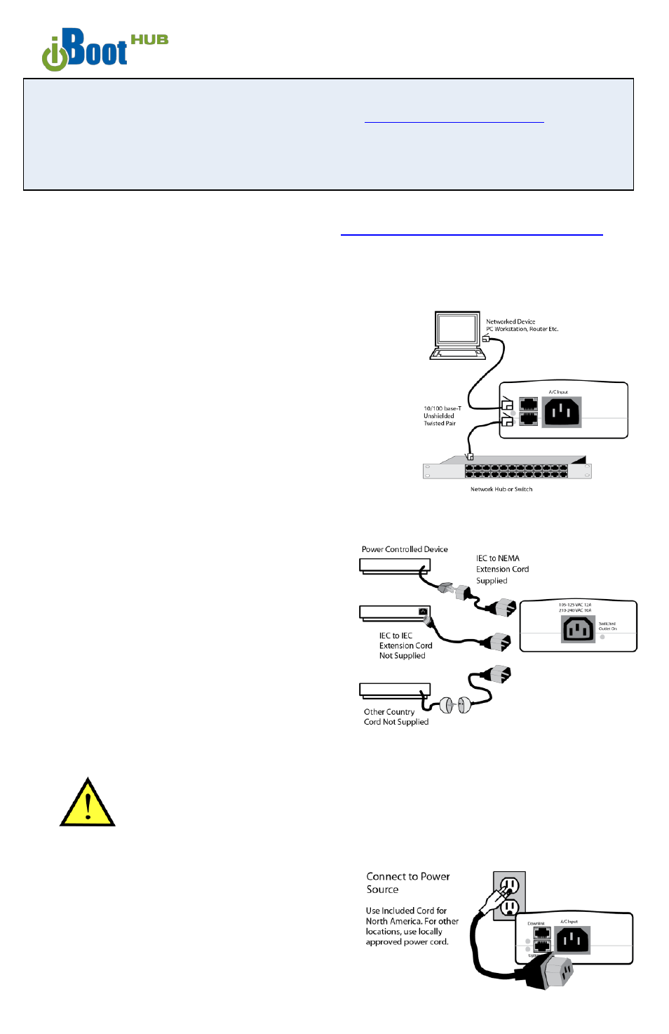
Connections
1. Connect Network. iBoot supports 10/100
Ethernet using unshielded twisted pair (Cat
5) cabling. Two network jacks, with built-in
Ethernet switch, are provided. They are
auto-sensing
for
10/100
and
Uplink/Downlink. A Link LED for each jack
indicates when the connection to the
network is properly established.
2. Connect Powered Device. Connect the
device to be powered ON and OFF to the
IEC receptacle marked A/C Outlet. An IEC-
320 to North American (NEMA 5-15) power
cord is included for connecting the iBoot
outlet to the device to be controlled. For
devices with IEC power connectors (fig 2B)
substitute an IEC-C13 to ICE-C14 Cord. For
countries with other power connectors,
substitute a suitable cord. These additional
cords are not supplied.
If the device has a power switch, turn it on,
to allow iBoot to control the power.
Make sure that the combined load of all controlled
devices does not exceed 12 Amps for 105-125VAC
or 10 Amps for 210-240VAC.
3. Connect Power Mains Connect the supplied
power cord to the connector labeled AC
Input, and the other end to your AC source.
If a power cord with a different terminating
plug is required, be sure it is properly rated
and meets all the required local electrical
standards.