Jumper settings, Chapter 2 jumper settings – DFI Q7A-551 User Manual
Page 9
www.dfi .com
Chapter 2 Hardware Installation
9
Chapter 2
Jumper Settings
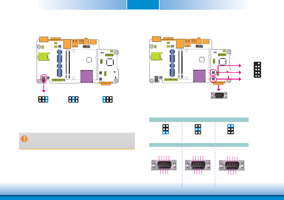
Panel Power Select
COM 1/COM 2 RS232/422/485 Select
JP2
JP2 is used to select the power supplied with the LCD panel.
Important:
Before powering-on the system, make sure that the power settings of JP2 match the
LCD panel’s specification. Selecting the incorrect voltage will seriously damage the
LCD panel.
1-2 On: +12V
3-4 On:+5V_standby
5-6 On: +3V_standby
(default)
1
6 4 2
5 3
1
6 4 2
5 3
1
6 4 2
5 3
JP4
JP6
JP4 (for COM 1) and JP6 (for COM 2) are used to configure the COM ports to RS232, RS422
(Full Duplex) or RS485. The pin functions of COM ports will vary according to jumpers’ setting.
JP4 (for COM 1)/ JP6 (for COM 2)
RS232
RS422
Full Duplex
RS485
COM 2
1-2 On: RS232
(default)
1
3
5
2
4
6
3-4 On: RS422
Full Duplex
1
3
5
2
4
6
5-6 On: RS485
1
3
5
2
4
6
COM 2
COM 2:
RS232/422/485
COM 1
2 1
9
COM 1:
RS232/422/485
DCD-
TD
RD
DT
R-
GND
RT
S-
RI
-
DSR
-
CTS-
1 2 3 4 5
6 7 8 9
RXD+
TXD+
RXD-
TXD- N.C.
N.C. N.C. N.C. N.C.
1 2 3 4 5
6 7 8 9
D
ATA
+
DA
TA
-
N.C. N.C. N.C. N.C.
N.C.
N.C.
N.C.
1 2 3 4 5
6 7 8 9