Chapter 2 – DFI CD951-C2800 User Manual
Page 18
www.dfi .com
18
Chapter 2 Hardware Installation
Chapter 2
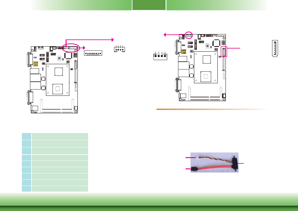
The 8-bit Digital I/O connector provides powering-on function to external devices that are
connected to these connectors.
8
1
1
4
+12V Ground 5VSB +5V
Digital I/O power
Digital I/O
Digital I/O Connector
Digital I/O Power Connector
Digital I/O Connector
Pins
Function
1
DIO0
2
DIO1
3
DIO2
4
DIO3
5
DIO4
6
DIO5
7
DIO6
8
DIO7
SATA (Serial ATA) Connectors
7
RXN
GND
TXP
TXN
GND
1
RXP
GND
SATA 2.0 3Gb/s
• Serial ATA port
- SATA0 port with data transfer rate up to 3Gb/s
• Integrated Advanced Host Controller Interface (AHCI) controller
SATA power
BIOS Setting
Configure the Serial ATA drives in the Integrated Peripherals submenu (“OnChip IDE Device”
section) of the BIOS. Refer to chapter 3 for more information.
The Serial ATA connectors are used to connect Serial ATA devices. Connect one end of the
Serial ATA data cable to a SATA connector and the other end to your Serial ATA device.
The system board package comes with a power cable that must be connected from the
system board’s peripheral power connector to the SATA drive’s power connector in order to
provide power to the drive.
Connect to the peripheral
power connector
Connect to the SATA drive
Connect to the SATA port
Features
SATA 0
1
4
+12V Ground Ground +5V