Hardware installation – DFI LR102-B18D/B18S User Manual
Page 42
Advertising
42
2
Hardware Installation
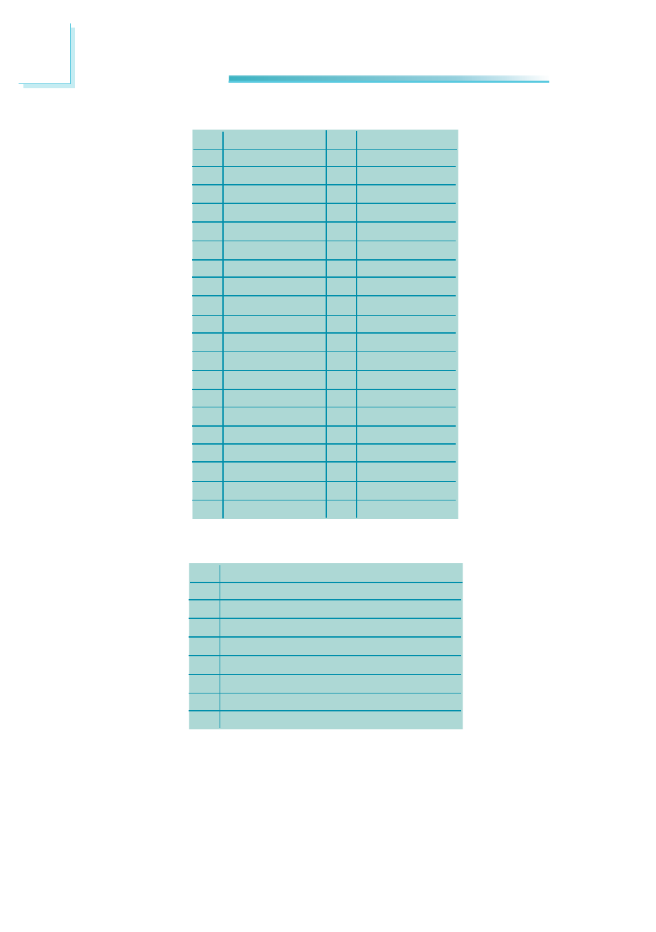
Pins
1
3
5
7
9
11
13
15
17
19
21
23
25
27
29
31
33
35
37
39
Function
GND
LVDS_Out3+
LVDS_Out3-
GND
LVDS_Out2+
LVDS_Out2-
GND
LVDS_Out1+
LVDS_Out1-
GND
LVDS_Out0+
LVDS_Out0-
GND
LVDS_CLK1+
LVDS_CLK1-
GND
LVDS_DDCCLK
LVDS_DDCDAA
Panel Power
Panel Power
Pins
2
4
6
8
10
12
14
16
18
20
22
24
26
28
30
32
34
36
38
40
Function
GND
N. C.
N. C.
GND
N. C.
N. C.
GND
N. C.
N. C.
GND
N. C.
N. C.
GND
N. C.
N. C.
GND
N. C.
N. C.
Panel Power
Panel Power
LVDS LCD Panel Connector
LVDS/Inverter Power Connector
Pins
1
2
3
4
5
6
7
8
Function
GND
GND
Panel Inverter Brightness Voltage Control
Panel Power
+3.3V
Panel Backlight On/Off Control
+12V
+12V
Advertising
This manual is related to the following products: