0 installation – Electro-Chemical Devices (ECD) R350D User Manual
Page 9
Model R350D
Page 3
2.0 INSTALLATION
Choose a location with easy access and out of
the direct sunlight. Mind the temperature
range when choosing the installation location.
2.1 MOUNTING
The R350 D remote display is designed for
wall mounting using #6 threaded screws. See
attached drawing for the hole dimensions.
2.2 WIRING
Warning!
• The electrical connection must only be carried out by authorized technical personnel.
• Technical personnel must have read and understood the instructions in this manual.
• Ensure that there is no voltage at the power cable before beginning the connection work.
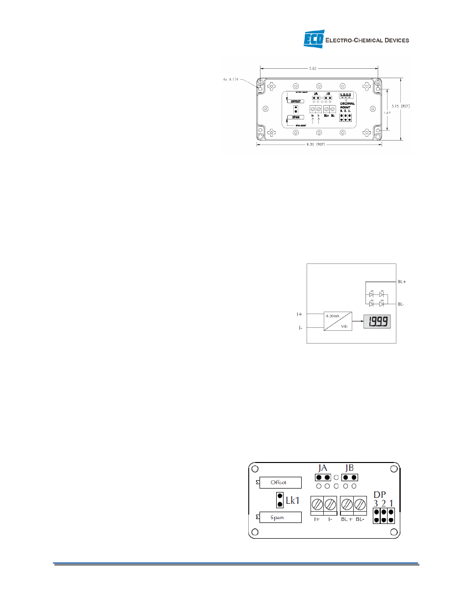
2.2.1 Wire Connections:
1.
I+ → positive 4-20 mA current input
2.
I- → negative 4-20 mA current input
3.
BL+ → 5V Positive power supply connection to the
optional LED backlighting.
4.
BL- → 5V Negative power supply connection to the
optional LED backlighting.
The optional LED backlighting requires a separate 5V DC power
supply. Ensure correct polarity when connecting.
2.2.2 Jumper Connections
A Jumper Link is used for setting the decimal point position on the display and for disabling the Offset
adjustment during a Calibration.
1.
No Jumper Link on DP 1, 2, or 3 → Display has no decimal point, 1000
2.
Jumper Link on DP 1 → Display shows 100.0
3.
Jumper Link on DP 2 → Display shows
10.00
4.
Jumper Link on DP 3 → Display shows
1.000
5.
Jumper Link on LK1 during Span
Calibration only