EM Acoustics AQ-10 switchmode amplifier User Manual
Page 14
AQ-10 Operating Instructions
Page 14
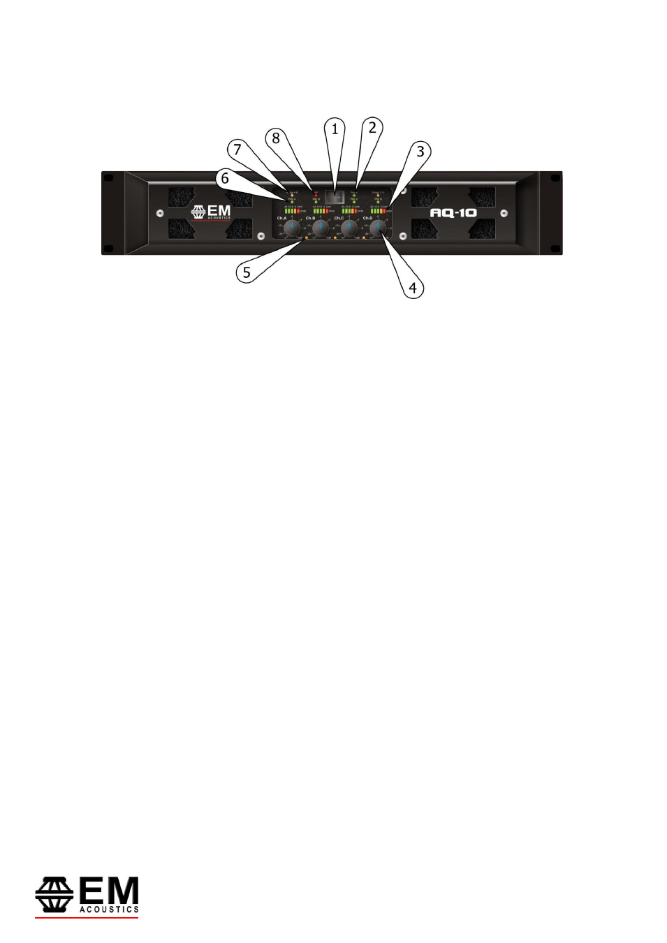
Operating Your Amplifier: Front Panel Controls and Indicators
1: Power Switch: This single pole switch turns the amplifier fully off (but does NOT isolate it
from the mains supply).
2: Power LED: This indicates when the amplifier is active. This does NOT indicate the
presence of a mains supply when the power switch is OFF.
3: Signal Meter and OCM indicators: These LED bar graphs show instantaneous level on
each channel to indicate proximity to the limiter threshold. Note that if the PRC system is in
operation on any channel, this will affect the readout shown on the respective meter.
The red LED in the meter will illuminate when the limiter threshold has been reached and
limiting is occurring. The output current monitor (OCM) may activate to limit the output
current of the amplifier channel - this can occur even if the amplifier has not reached clipping
point.
The OCM indicator can operate independently of the bar graph meter. Typical conditions that
may trigger the OCM circuitry would be very low load impedance, or high subsonic or VHF
levels.
4: Attenuation Controls: These are analogue controls allowing precise level settings. Note
that in bridged (mono) mode some controls may be inactive.
5: Link LED: This indicates if the channel is linked to its immediate neighbour. The link
switches are on the rear panel – see page 16 for details.
6: PRC LED: This illuminates if the Power Reduction Control has been enabled on the
respective channel. PRC switches are on the rear panel – see page 16 for details.
7: Bridge LED: This illuminates when a channel pair have been switched into bridged
(mono) mode (channel A+B or C+D). Note that the partner channel’s LEDs and controls are
disabled when a pair of channels are bridged. Bridge switches are on the rear panel – see
page 16 for details of how to connect your speaker to a bridged channel pair.
8: A/P (Auto Protect) LED: If a condition exists, either internally or externally, that could
cause damage to either the amplifier or the speakers, the protection circuit will disengage the
outputs and the A/P LED will illuminate. The amplifier will continue to be monitored and
depending on the type of fault, will either reset after the fault has cleared or require manual
resetting by switching off at the mains switch and then on again after a few seconds.