11 hydraulic, mechanical and electrical duty – Flowserve Twin Screw Rotary User Manual
Page 34
TWIN SCREW PUMPS. ORIGINAL USER INSTRUCTIONS. ENGLISH. 71569243 – 07/10
Page 31 of 53
®
5.11 Hydraulic, mechanical and electrical
duty
This product has been supplied to meet the
performance specifications of your purchase order,
however it is understood that during the life of the
product these may change. The following notes may
help the user decide how to evaluate the implications
of any change. If in doubt contact your nearest
Flowserve office.
5.11.1 Differential pressure
Each operator should study the performance curve
supplied with the particular unit in question. This
curve should indicate the design pressure, capacity,
speed and viscosity (condition of service, COS,
pumping conditions) for which the unit was sold.
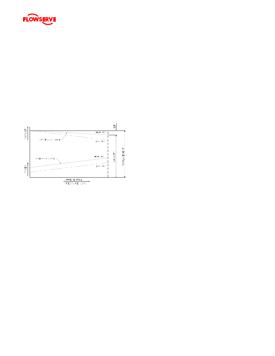
Figure 5
Any positive displacement pump is suitable for a wide
range of operating conditions, but to meet a specific
condition of service the pumping rotors must be the
correct pitch and rotate at the correct speed. When
the rotor pitch, speed and viscosity are known, a
single curve can be drawn which shows the
relationship between differential pressure and
capacity. (Refer to Fig. 5). Barring suction, system
or mechanical troubles, the pump will operate at
some point on this curve.
To operate at some point not on the capacity-
differential pressure curve would require a different
speed or a different viscosity liquid being pumped.
A positive displacement pump has a general
characteristic that the flow decreases as the
differential pressure across the pump increases. The
pump operates against the resistance of the system
and does not generate head as a centrifugal pump
does. It will continue to operate if the system
resistance increases (closing of discharge valve),
building up internal pressure until failure of pressure
containing parts. A suitably sized relief valve should
be present in the discharge piping between the
discharge valve and the pump.
Again, it should be noted that a positive displacement
pump should never be started against a closed
discharge valve nor should the discharge valve be
closed prior to stopping the pump.
The capacity the pump produces at zero differential
pressure (system resistance) is called the
displacement of the pump and is not dependent on
the viscosity of the liquid. It is a function of the size
of the pump, the pitch of the pumping rotors and the
pump speed. As the differential pressure increases,
recirculation or slip is produced as liquid is forced
back to suction through the internal clearances of the
pump. The slip increases proportionally to the
differential pressure. The amount the slip increases
is a function of the viscosity of the liquid. The higher
the viscosity of the liquid, the less the slip. The
displacement less the slip is the capacity the pump
will produce.
Normal operation of the pump will eventually produce
wear on internal components resulting in increased
internal clearances. This will increase the slip and
reduced performance may be experienced. At this
point, rotating components may have to be
refurbished or replaced to maintain original
performance.
Never operate a positive displacement pump to any
pressure in excess of the maximum pressure
indicated on the nameplate. If the original conditions
must be changed for any reason, consult Flowserve.
5.11.1 Specific gravity (SG)
Pump capacity and total head in metres (feet) do not
change with SG, however pressure displayed on a
pressure gauge is directly proportional to SG. Power
absorbed is also directly proportional to SG. It is
therefore important to check that any change in SG
will not overload the pump driver or over-pressurize
the pump.
5.11.2 Pump speed
Changing pump speed effects flow, power absorbed,
NPSH
R
, noise and vibration. Pump displacement
varies in direct proportion to pump speed, The new
duty, however, will also be dependent on the system
curve. If increasing the speed, it is important
therefore to ensure the maximum pump working
pressure is not exceeded, the driver is not
overloaded, NPSH
A
> NPSH
R
, and that noise and
vibration are within local requirements and
regulations.