Flowserve VCT User Manual
Page 10
USER INSTRUCTIONS APM, APMA and APH MX0301 - 07/03
Page 10 of 32
®
and as in consequence, catastrophic failure to the
top parts of the motor.
If the phase sequence of the incoming motor power
cables is not positively known and the motor is to
be “bumped” for rotation check, the ratchet pins
must be removed from the pin carrier, to avoid the
expected damage to the non reverse device.
The pins removal is under customer or motor
installer responsibility.
Whenever
the
dismantling
of couplings
is
necessary, the use of witness marks will assure a
balanced condition when assembly is complete.
If maintenance work has been
carried out to the site's electricity supply, the
direction of rotation should be re-checked as above
in case the supply phasing has been altered.
It is recommended that records be kept pf the
steady state uncoupled vibration and bearing
temperatures to use for comparison with coupled
and loaded conditions, and to provide a data base
for judging the motor’s performance in the future.
These records should be permanently retained for
reference.
5.4 Guarding
Guarding is supplied fitted to the pump set. If
this has been removed or disturbed ensure that all
the protective guards around the pump coupling and
exposed parts of the shaft are securely fixed.
5.5 Rotor Setting
Before pump start up, it is required
adjust the impeller setting and avoid rubbing
between impeller and impeller liner which can
damage severely the pump, Rotor setting is
specified on pump nameplate and pump outline
drawing.
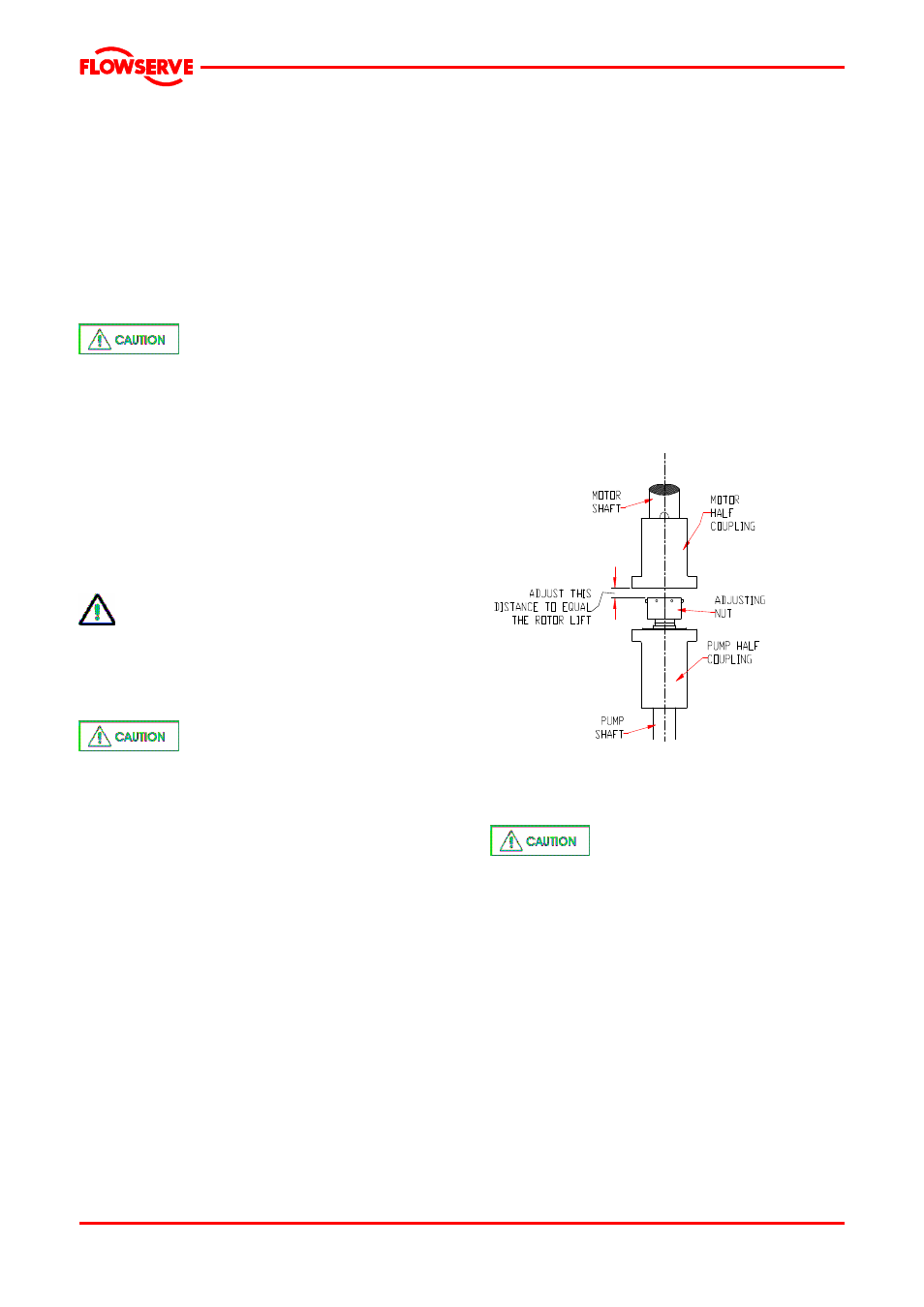
Follow next procedure in order to adjust the rotor
setting:
a) Fit motor half coupling on motor shaft.
b) Fit split ring on motor shaft and move
motor half coupling until it covers the split
ring.
c) Fit pump half coupling on the pump top
shaft.
d) Fit adjusting nut on the pump top shaft.
e) Adjust separation between adjusting nut
and motor half coupling at rotor setting
specified on nameplate; Use feeler gages.
f) Turn motor half coupling so bolt holes will
line up with the bolt holes in the pump half
coupling
g) Insert two of the coupling bolts and tighten
progressively until secure, thereby closing
the gap above the adjusting nut and raising
rotor to running position.
h) Insert the remaining bolts and tighten them
securely.
i)
Check for free rotation of driver and pump
shaft. (See coupling detail in section 8)
j)
If mechanical seal is supplied, the set
screws of drive collar must be tighten in
this moment.
5.6 Starting the pump
a) CLOSE the outlet valve, two –speed motor
operator with valve opening and slow closing.
Generally
15/45
second
timing
works
satisfactorily for most pump systems. 15
second to open , 45 second to close totally the
valve. A single speed valve motor, most
economical,
at
60
second
should
be
satisfactory.
b) PRE-OPEN pump valve to 30 degrees with
motor interlocked to start and stop position.
The system can be primed or unprimed. If
unprimed, system downstream should be fully
opened and vented while hold valve to 30
degrees until system is stabilized, motor
reaches rated speed and / or discharge piping
is completely full.
c) On Fully Prime System using a 15/45 second
valve
operator.
Start
pump
and
valve
simultaneously.