2 suction piping – Flowserve LNGT User Manual
Page 19
LNGT USER INSTRUCTIONS ENGLISH 00083107 02-08
Page 19 of 48
®
4.4.2 Suction piping
Refer to the diagrams below for typical designs of
suction piping for both flooded suction and
suction lift.
a) The inlet pipe should be one or two sizes
larger than the pump inlet bore and pipe
bends should be as large a radius as
possible.
b) Pipe work reducers should be conical and
have a maximum total angle of divergence of
15 degrees.
c) On suction lift the piping should be inclined
up towards the pump inlet with eccentric
reducers incorporated to prevent air locks.
d) On positive suction, the inlet piping must
have a constant fall towards the pump.
e) Flow should enter the pump suction with
uniform flow, to minimize noise and wear.
This is particularly important on large or high-
speed pumps which should have a minimum
of five diameters of straight pipe on the pump
suction between the elbow and inlet flange.
See section 10.3, Reference 1, for more
detail.
f) Inlet strainers, when used, should have a net
`free area' of at least three times the inlet pipe
area.
g) Do not install elbows at an angle other than
perpendicular to the shaft axis. Elbows
parallel to the shaft axis will cause uneven
flow.
h) Except in unusual circumstances strainers
are not recommended in inlet piping. If
considerable foreign matter is expected a
screen installed at the entrance to the wet
well is preferable.
i)
Fitting an isolation valve will allow easier
maintenance.
j)
Never throttle pump on suction side and
never place a valve directly on the pump inlet
nozzle.
Typical design – flooded suction
Discharge
isolating
valve
Non
return
valve
Concentric
conical
reducer
Eccentric
conical
reducer
Suction
isolating
valve
Slope up from
pump suction
Note:
Ideally reducers should be limited to one pipe diameter
change,
ie 150 mm [6 in.] to 200 mm [8 in.]. Must have a maximum
total angle of divergence of 15 degrees.
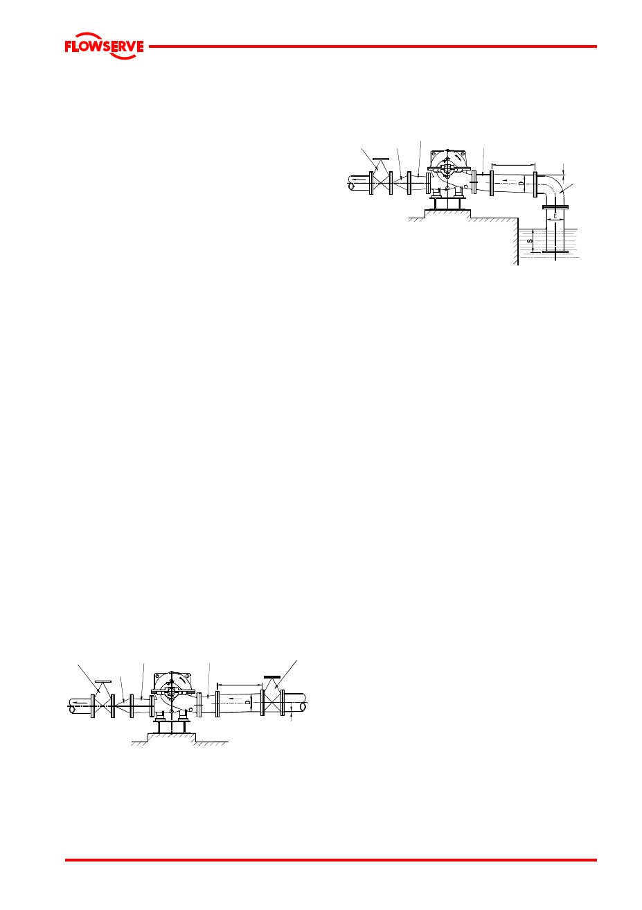
Typical design – suction lift
L o n g
r a d i u s
b e n d
S l o p e d o w n
f r o m p u m p
s u c t i o n
>5D
E c c e n t r i c
c o n i c a l
r e d u c e r
D i s c h a r g e
i s o l a t i n g
v a l v e
C o n c e n t r i c
c o n i c a l
r e d u c e r
N o n
r e t u r n
v a l v e
Notes:
1. S = Minimum submergence >3E.
2. Ideally reducers to be limited to one pipe diameter change,
ie 150 mm [6 in.] to 200 mm [8 in.]. Must have a maximum
total angle of
divergence of 15 degrees.
>5D