2disassembly, 1nomenclature – Flowserve ISC1BX User Manual
Page 2
2
Disassembly
When disassembling seal, inspect for conditions which may have caused the
need for the seal to be removed from service. If seal was removed due to
premature failure, determine what conditions caused that failure and correct any
problems prior to returning the repaired seal to service. For assistance with seal
failure analysis, please contact your Flowserve representative.
2
© Copyright 2000 Flowserve Corporation
These instructions are written for trained, experienced technicians familiar with the basic
principles and tools involved in the installation, care and service of mechanical seals and seal
support systems. A complete reading of these instructions by personnel in contact with the
equipment is essential to safety. Incorrect installation, operation or maintenance can result in
personal injury or death to personnel and damage to the equipment.
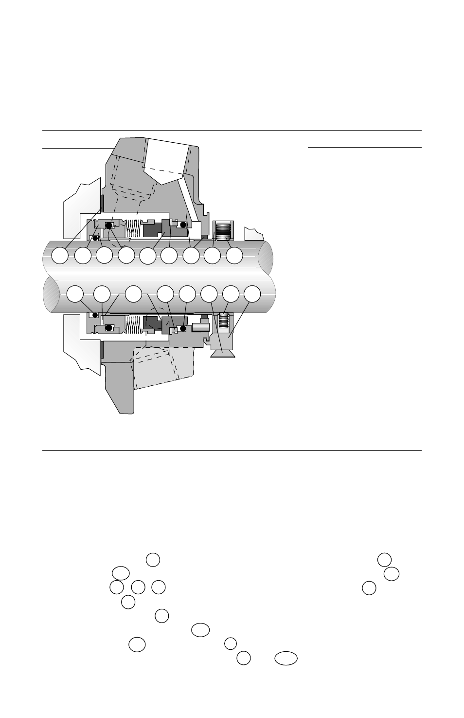
1
Nomenclature
Note: Primary seal O-rings (P and 6) are
the same size and cross section.
34
Bellows Assembly
3A
Mating Ring
P
Mating Ring O-Ring
6
Bellows O-Ring
11
Sleeve O-Ring
G
Gasket
1
Gland Assembly
1B
Gland Drive Ring
CT
Centering Tab
K
Centering Tab Cap Screw
SL
Sleeve Assembly
M
Vibration Dampener
M1
Bellows Vibration Dampener
10A
Driver Ring
9
Sleeve Collar
13
Cup Point Set Screw
13A
Quarter Dog Set Screw
Table 1
Figure 1
Seal Parts that are always replaced
• Bellows Assembly
34
• Mating ring
3A
• All O-rings
P , 6 , 11
• Gland gasket
G
• Vibration dampener
M
• Bellows Vibration dampener
M1
• Centering tabs
CT
and cap screws
K
• Cup point and quarter dog set screws
13
and
13A
Reconditionable Seal Parts
• Gland assembly
1
• Sleeve assembly
SL
• Sleeve collar
9
G
SL
M
M1
3A
1
13
9
10A
11
6
34
P
K
13A
CT
1B