Seal chamber requirements, Figure 1 introduction, 1equipment check – Flowserve Allpac MP User Manual
Page 2
2
© Copyright 2002 Flowserve Corporation
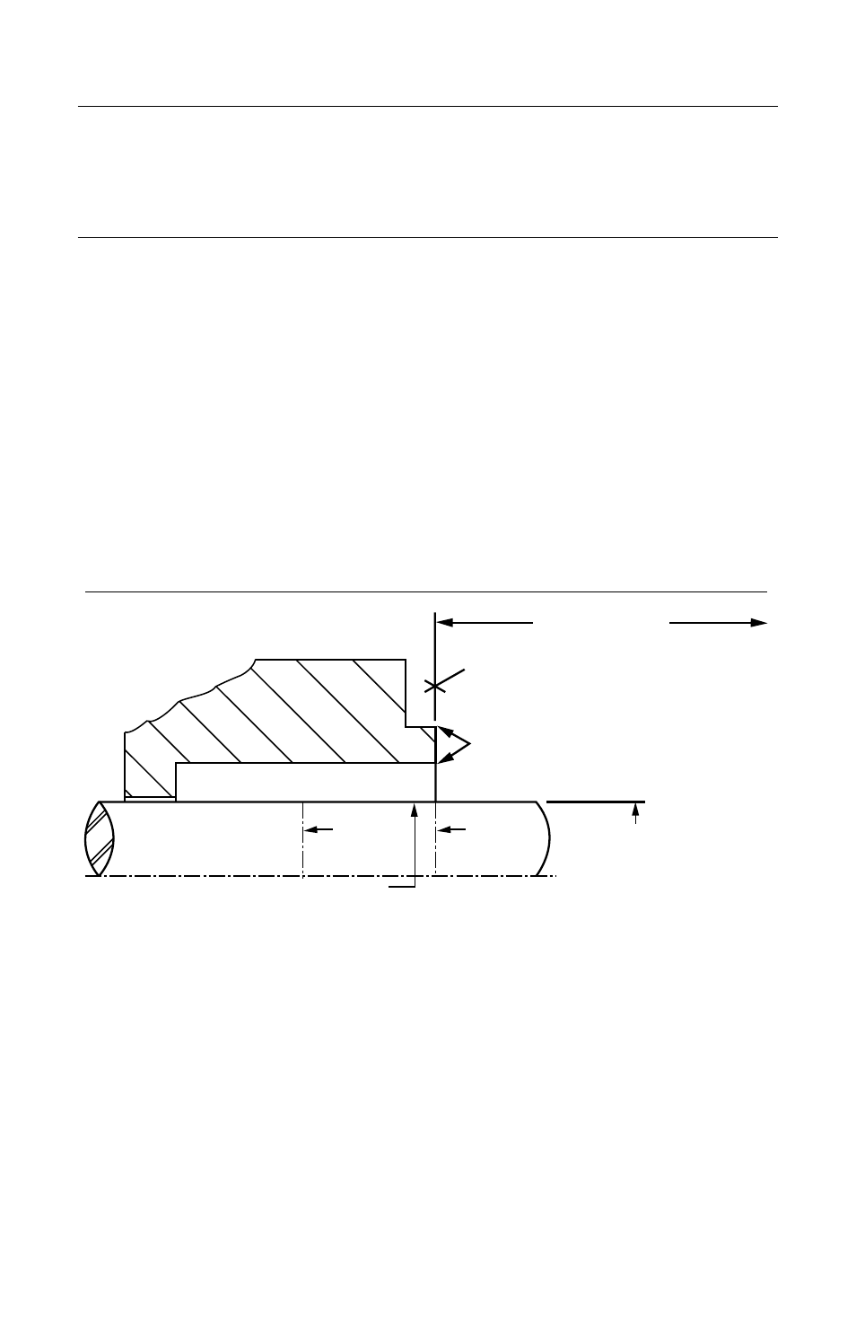
To first obstruction
Face of seal housing to be square to the axis
of the shaft to within .005 inch (0.13 mm) FIM
and have a
√
63
µ
inch (1.6
µ
m) R
a
finish or
better
Concentric to within .005 inch (0.13mm) FIM
of shaft or sleeve O.D.
• Bearings must be in good condition.
• Maximum lateral or axial movement of shaft (end play) = .010 inch (0.25mm) FIM
• Maximum shaft runout at face of seal housing = .003 inch (0.07mm) FIM
• Maximum dynamic shaft deflection at seal housing = .002 inch (0.05mm) FIM
Seal Chamber Requirements
Seal housing bore to have a
√
125
µ
inch
(3.2
µ
m) Ra finish or better
Sleeve or shaft finish to be
√
32
µ
inch (0.8
µ
m) R
a
or better
Scribe
Mark B
Scribe
Mark A
+.000 inch (+.000mm) API 610
Figure 1
Introduction
The Allpac MP is a dual-inline, cartridge seal specifically designed for multiphase twin-
screw pumps. Four mechanical seal assemblies are installed on one pump. Each seal is
identical; they are designed to fit in any location on the pump.
1
Equipment Check
1.1
Follow site safety regulations prior to equipment disassembly.
• Lock out motor and valves
• Wear designated personal safety equipment
• Relieve any pressure in the system
• Consult site MSDS files for hazardous material regulations
1.2
Disassemble equipment to allow access to seal installation area.
1.3
Remove all burrs and sharp edges from the shaft or sleeve including sharp edges
of keyways and threads. Replace shaft or sleeve if worn in the sleeve gasket
area. Make sure the seal housing bore and face are clean and free of burrs.
1.4
Check requirements for shaft, sleeve, and seal housing, see Figure 1.
1.5
Check assembly drawing included with the cartridge seal for materials of construc-
tion, dimensions, and piping connections.
1.6
Check shaft or sleeve O.D., box bore, and distance to the first obstruction to
ensure that they are dimensionally the same as shown on the seal assembly
drawing.
1.7
Check gland pilot and bolt holes to ensure they are adaptable to the equipment
and are the same as shown on the assembly drawing.