Flowserve ISC2BB User Manual
Page 8
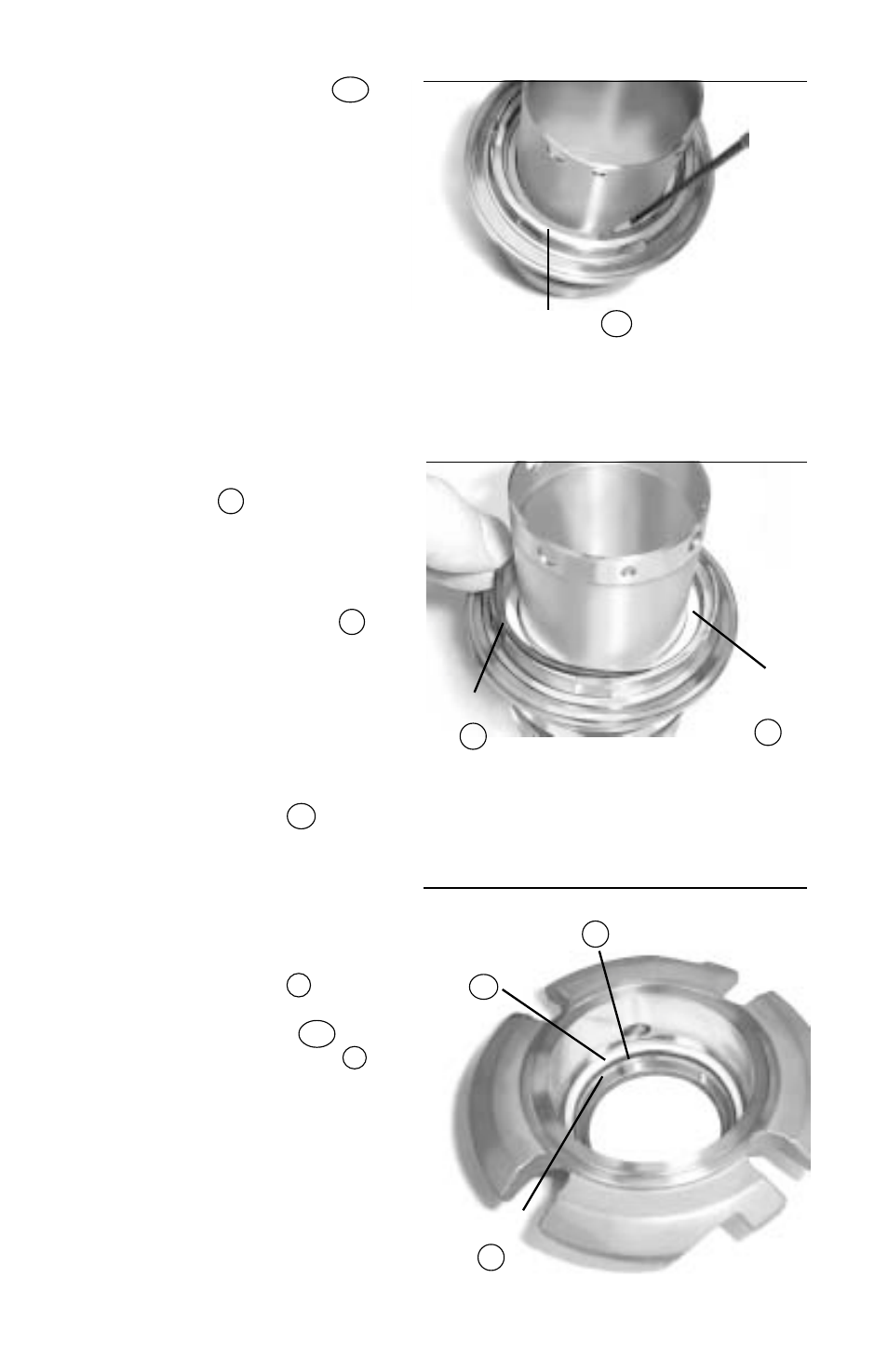
4.12 Insert the retaining ring
RR
into the groove in the sleeve
assembly while pressing
down on the rotor carrier.
Make sure that the retaining
ring snaps completely into
the groove in the sleeve
assembly. (
Figure 14
)
4.13 Insert the outboard vibration
dampener
M
into the rotor
carrier. Make sure that the
vibration dampener is fully
seated at the bottom of the
rotor carrier. Place the
outboard bellows O-ring
6
in the O-ring groove of the
rotor carrier, which is behind
the surface with two drive
flats. (
Figure 15
)
4.14 Repeat steps 4.7 through 4.9
to assemble the outboard
bellows assembly
34
into
the sleeve/rotor carrier
assembly.
Assemble the outboard
mating ring O-ring
P
and
the outboard bellows
vibration dampener
M2
into the gland assembly
1
.
(
Figure 16
)
Figure 14
8
Retaining Ring
RR
Figure 15
O-ring
6
Vibration
Dampner
M
Figure 16
Gland
Drive Ring
1B
Vibration
Dampener
M2
O-ring
P