Foreword, Pressure containing fasteners, How to specify – Flowserve BTV 2000 Lined Butterfly Valve User Manual
Page 3
FOREWORD
The Flowserve Corporation, Flow Control Division has
established this Installation, Operating and Maintenance
Manual to facilitate field installation, operation and repair of
BTV-2000 and BUV-2000 Series Butterfly Valves.
It is recommended that questions or concerns regard ing the
processes described in this manual be directed to Flowserve
Field Sales Representative, authorized stocking distributor
or the Flowserve Corporation, Flow Control Division.
Part numbers referenced in the following sections are
available from the Flowserve Corporation, Flow Control
Division.
Only Flowserve replacement repair parts and assembly
tooling made or designed by the Flowserve Corporation
should be used.
PREssuRE COntaining FastEnERs
Material Selection
Selecting the proper fastener material is the ultimate
responsibility of the customer because the supplier does
not typically know in what service the valves will be used
or what elements may be present in the en vironment.
Flowserve normally supplies B7 (carbon steel) for ductile
cast iron and carbon steel valves. For stain less steel and
high alloy valves, B8 (stainless steel) fasteners are supplied
as standard. All fasteners used must have a minimum yield
strength of 40,000 PSI, a minimum elongation of 12% and
be compatible with the process fluid. Determining compati-
bility to the process fluid goes beyond a material being
resistant to general corrosion because the more important
con sid eration is a material’s resistance to stress corrosion
cracking. Depending on the service, it may make sense to
use B7 fasteners on high alloy valves. One such service
would be marine environments because of stainless steel’s
susceptibility to stress corrosion cracking in chloride
environments. Another key aspect of fasteners is frequent
visual inspection. Because of the common practice of using
steel fasteners rather than stainless steel to avoid chloride
stress corrosion cracking, visual inspection is recom-
mended to monitor the general corrosion of these fasteners.
If jacketing or insulation is used on a valve, it must be
periodically removed for visual inspection of the fasteners.
If you wish assistance in determining the proper fasteners
to use, please refer to the attached chart or contact the
Flowserve Materials Engineering Group at (937) 226-4475.
Design & Type
The Flowserve valve design standards adopt ANSI B18.2.1
(1981) as the standard for fastener type and design. This
national standard requires that finished hex “head” cap
screws be used when the head of the fastener is turned. A
finished hex “head” cap screw and a heavy hex cap screw
have a bearing surface under the head to minimize frictional
resistance during tightening. They also comply to qualified
body dimen sions and fully formed head dimensions.
Cookeville Flow Control Division’s policy is to use finished
hex “head” and heavy hex “head” cap screws for all
pressure retaining fasteners. This includes top caps, packing
adjusters, plug adjusters, bottom caps, body halves or other
pressure retaining components. Compliance is made with
ANSI B18.2.2 (1987), Square and Hex Nuts, when studs and
heavy hex nuts are required. Additional information on these
items may be obtained from the Flowserve Corporation,
Cookeville Flow Control Division, Cookeville, Tennessee.
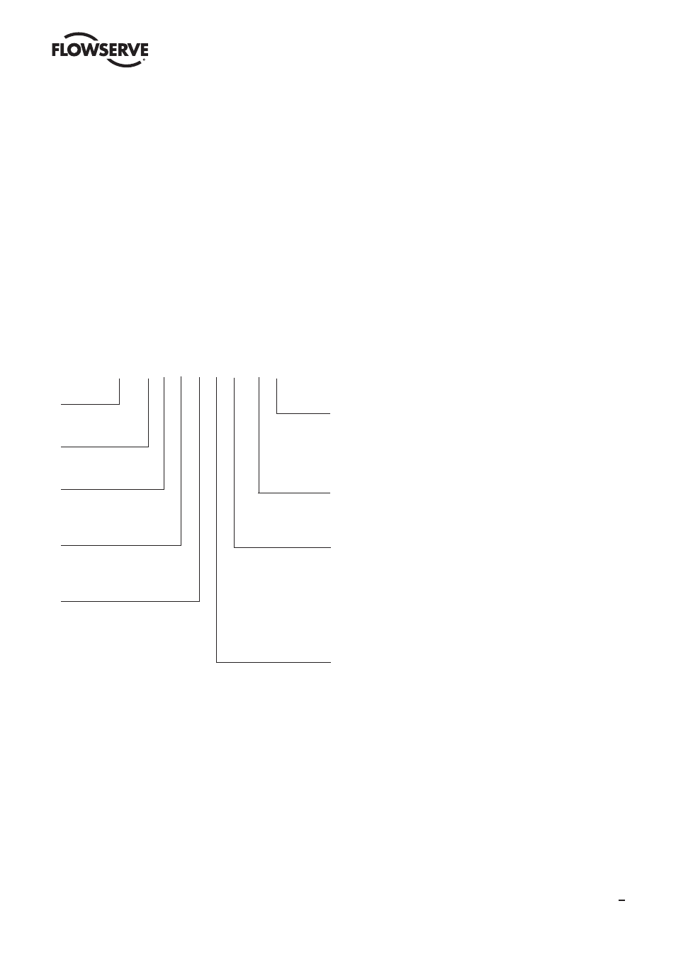
HOW tO sPECiFY
12 - B T L 4 8 1 - V P1
SIZE
2” - 24”
VALVE TYPE
B = Butterfly
LINER MATERIAL
T = PTFE
U = UHMWPE
BODY STYLE
W = Wafer
L = Lug
BODY MATERIAL
4 = A395 GR. 60-40-18
(2” - 24”)
DCI
1 = A744 GR. CF8M
(All Sizes)
D4
+ Coated Disc Insert Material: A395 GR. 60-40-18 (2”-24”) DCI
*Registered Trademark of Avesta AB
FLANGE
DRILLING
Blank = ANSI 150
P1 = DIN PN10
P6 = DIN PN16
ELASTOMER
SEALS
Blank = Silicone
V = Viton
ACTUATOR
0 = 10 Position
Locking Lever
1 = Enclosed Gear
9 = Bare Stem
(Specify Type)
STEM & DISC
MATERIAL
0 = A351/A744 GR. CD4M-CU
D100
1 = A351/A744 GR. CF8M
D4
2 = A351/A744 GR. CN7M
D20
3 = A494 GR. M-35-1
DMM
5 = A494 GR. N7M
DC2
6 = A494 GR. CW6M
DC3
7 = B367 GR. TI-PD 8A
TIP
8 = PFA COATED
DIPA
9 = UHMWPE COATED
DIPE
S = A351/A744 GR. CK-3MCuN 254 SMO*
3
BTV/BUV 2000