Flowserve CV10 User Manual
Page 6
6
Danger
Consider the relevant regulations for the
prevention of accidents. Do not exchange the
main valve seal unless the tank container is
completely empty and degassed. Be careful
when taking parts out of the water bath – they
are hot (risk of burns and scalds).
Replacement of main valve seal
(Fig. 3)
1. Remove valve disc.
2. Use two needles or similar tools to lever the
O-ring
Y
out of the valve disc. Apply light
smear of lubricant to new O-ring.
3. Heat valve disc
H
and O-ring
Y
in the
water bath to a temperature of 90 – 95 °C.
4. Insert and press O-ring into groove.
5. Re-install valve disc.
Replacement of bearing bush and
stem sealing
(Fig. 2)
1.
Dismantle spring and operating lever as
described.
2.
Loosen socket-head cap screw
G
so that
the lever can be shifted on the inner stem
hexagon.
3.
Remove oval flange
I
.
4.
Attach operating lever by means of socket-
head cap screw to stem
P
, pull stem out
of body
A
.
5.
Remove bushes
K
and
O
.
6.
Clean location hole for stem. Do not
damage sealing surfaces for O-rings
N
and
M
.
7.
Insert new bushes
K
and
O
.
8.
Apply lubricant to O-rings
N
+
M
and to
rings
L
and push them onto the stem.
Consider correct order and right position.
Remove any surplus lubricant on the stem
bearing surfaces.
9.
Push stem with rings onto body
A
by to
and fro motions and then over the lever.
The socket-head cap screw
G
must
coincide with the countersunk part of the
stem.
10. Tighten screw
G
with a torque of
7.5 + 0.5 Nm.
11. Mount oval flange
I
, tighten screws
J
with a torque of 7.5 + 0.5 Nm.
12. Refit and adjust spring and operating lever.
Fitting of lever for release cord
(“remote operator”)
(Fig. 4)
1. Dismantle spring and lever as described.
2. Insert lever
Z
for remote quick-closing onto
stem
P
.
3. Refit spring and operating lever.
4. Laying of release cord on site by container
manufacturer.
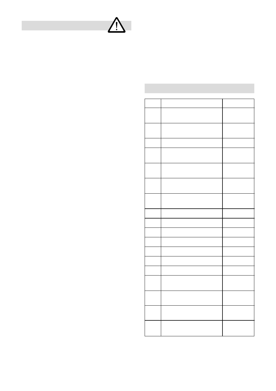
Spare parts
Item
Designation
Order No.
K
Collar bush
048759
14 x 18 x 18
O
Collar bush
048 761
22 x 15 x 32
S
Reel
048 762
T
Socket-head cap bolt
048 763
M 10 x 28
G
Socket-head cap bolt
012 488
M6 x 8
J
Hexagon-head cap bolt
013 821
M6 x 10
V
Socket-head cap bolt
011 555
M8 x 35
★
N
O-ring
048 766
★
M
O-ring
048 765
★
Y
O-ring (main seal)
048 771
★
L
Ring
048 767
X
Locking clip
048 984
Q
Lever extension
048 776
W
Pin
013 067
U
Spring (with sea-water
049 022
resistant coating)
Assembly parts:
049 053
nuts and bolts
Assembly parts:
048 780
gasket
Lever for release
049 061
cord (accessory)