Parts list cw 41/4, Dismantling, Tools required – Flowserve CW41 Control Valves User Manual
Page 3
Parts List CW 41/4
(for parts differing from those of CW 41)
Item No.
Description
Stock code
Number
Material
Hints
2
Valve cone:
“r” cone complete
DN 25 mm (1")
DN 40, 50 mm (1½, 2")
DN 80, 100 mm (3, 4")
184348
184351
184352
1
Satinless steel (1.4312)
For “r” cone only:
O-ring of FKM (Item No. 2.1)
DN 25 mm (1") No. 031151
DN 40, 50 mm (1½, 2") No. 031152
DN 80, 100 mm (3, 4") No. 031788
“s” cone
DN 25 mm (1")
DN 40, 50 mm (1½, 2")
DN 80, 100 mm (3, 4")
030984
030987
030990
1
Satinless steel (1.4312)
3
Thermostat complete:
“w” thermostat
DN 25 mm (1")
DN 40, 50 mm (1½, 2")
DN 80, 100 mm (3, 4")
184427
1
2
3
Body and Pin:
Austenitic satinless steel
(1.4571)
“n” thermostat
DN 25 mm (1")
DN 40, 50 mm (1½, 2")
DN 80, 100 mm (3, 4")
184428
1
2
3
“k” thermostat
DN 25 mm (1")
DN 40, 50 mm (1½, 2")
DN 80, 100 mm (3, 4")
184429
1
2
3
6
Setting device complete
with extension
031135
1
S.S. (1.4305 / 1.4104)
15
15.1
Pressure gauge with extension
Pressure gauge, water-proof
031154
033779
1
1
Extension: S.S. (1.4104)
Measuring range:
0 – 6 barg (0 – 85 psig)
16
16.1
Thermometer with extension
Thermometer 105 mm long
184598
184597
1
1
Extension: S.S. (1.4104)
Measuring range: –30 °C to 100 °C
Dismantling
Exchange of Valve Cone / Thermostat
1. Isolate the valve from pressure. Shut off feed line and
in the case of back pressure also return line.
2. Remove nuts
7.5.
Attention: Spring 7.1 is under tension!
Reduce tension by turning adjusting key
11 to the left.
Be careful when loosening nuts. Remove cover
7.3,
and take out spring
7.1.
3. Turn adjusting key
11 to the right until a resistance is
felt to push valve cone
2 upwards.
4. Take out valve cone
2 from above.
To exchange thermostats
3 remove retaining ring 4.
(Number of thermostats:
DN 25 mm (1") = 1 off;
DN 40, 50 mm (1½, 2") = 2 off;
DN 80, 100 mm (3, 4") = 3 off.)
The setting device
6 is provided with a righthand thread.
Normally, the setting device need not be dismantled.
Reassembly in reverse order.
Take care that sealing surfaces are clean, replace gasket
7.2. Valves with “r” cone: Ensure that O-ring 2.1 is un-
damaged, replace if necessary.
Torques required for tightening nuts 7.5 at room tem-
perature
DN 25, 40, 50 mm (1, 1½, 2") 15 Nm
DN 80, 100 mm (3, 4")
25 Nm
Tools Required
Spanners for items
7.5 DN 25, 40, 50 mm (1, 1½, 2") A.F. 13 mm
DN 80, 100 mm (3, 4")
A.F. 17 mm
6 A.F. 32 mm
15 A.F. 14 mm
16 A.F. 19 mm
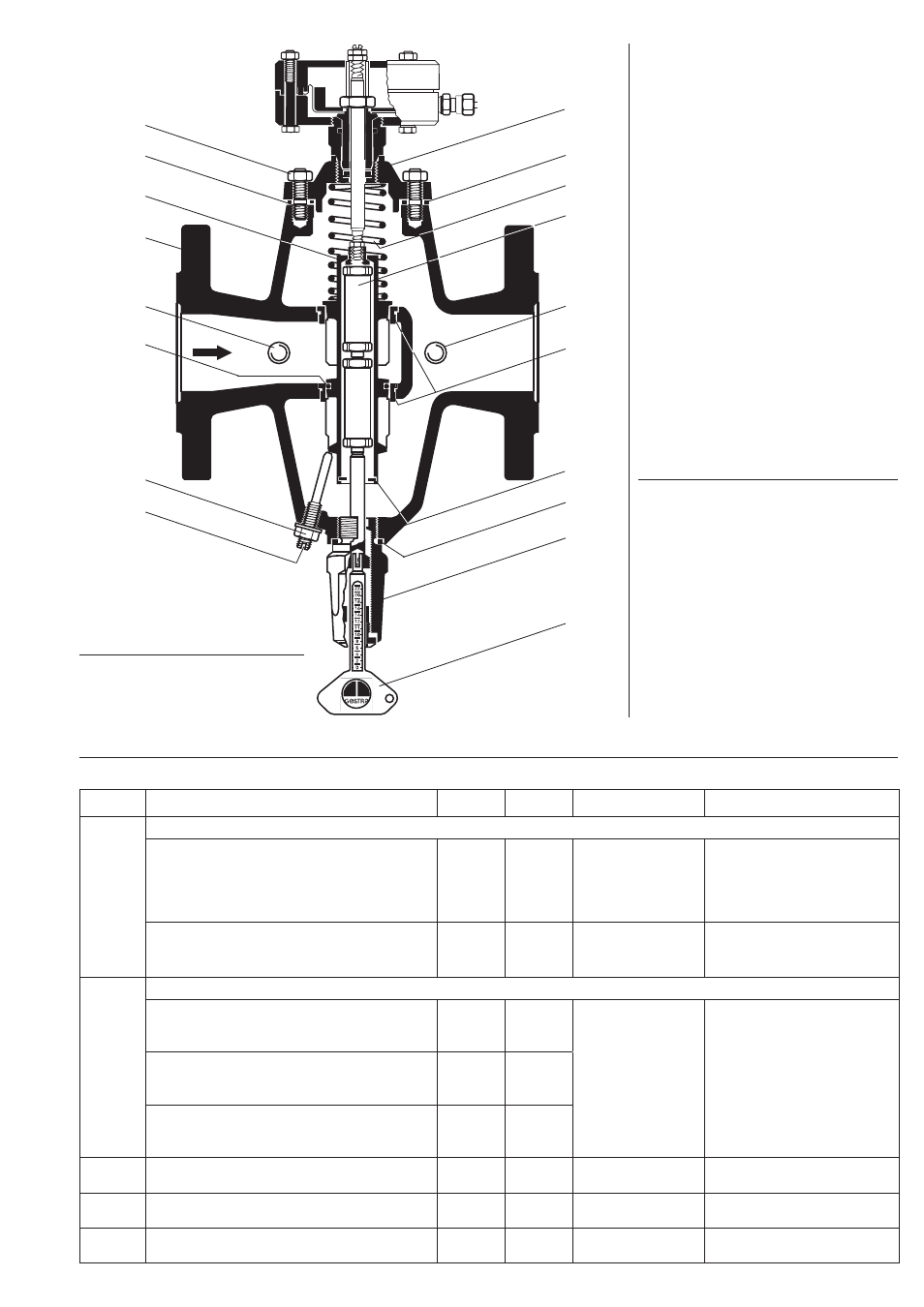
Shown
CW 41 DN 40, 50 mm (1½, 2")
A
= Connection for pressure gauge
(item 15), ¼" BSP
B
= Connection for thermometer
(item 16), ¼" BSP
A
B
7.3
7.2
7.1
3
7.9 + 7.10
1.1
4
11
6
5
7.5
7.4
2
1
7.9 + 7.10
2.1
7.8
7.6