Flowserve 035 000 Series User Manual
Page 7
7
Flow Control Division
Kammer Control Valves
6.4.3
Unscrew the coupling insert until the yoke rods are
raised from the lower yoke plate by around 2 mm.
NOTE:
Ensure that the plug assembly is not rotated
with the plug seated. This may cause irreparable
damage to the seating faces.
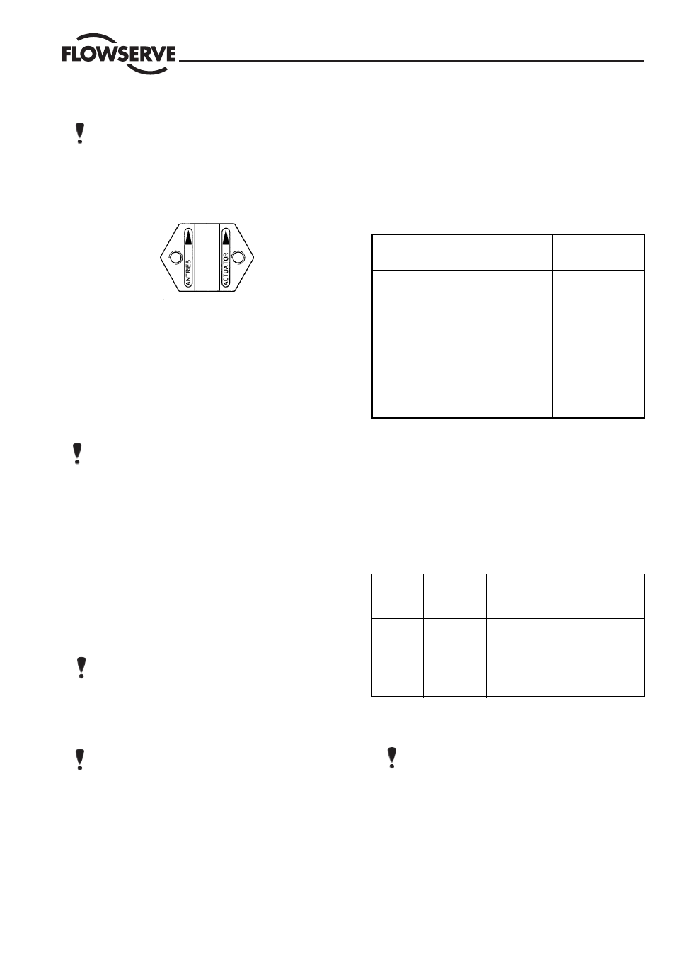
6.4.4
Refit the coupling, ensuring that the arrows,
embossed on the coupling halves, point upward
towards the actuator, and secure with 2 retaining
screws.
6.4.5
Apply supply pressure resp. vent actuator to half stroke
and refit and tighten yoke rod retaining nuts (15).
6.4.6
Connect all tubing.
7
DISASSEMBLE AND ASSEMBLE VALVE
7.1
Disassemble Valve
(see Fig. 2)
7.1.1
Remove bonnet flange bolting and raise bonnet and
plug assembly.
NOTE:
heavy assemblies may require a hoist
7.1.2
Unscrew seat ring using seat ring tool and carefully
press plug stem evenly out of the upper body.
7.1.3
With valves DN 80 / kv 63 and larger, the plug head
can be unscrewed (see Fig. 3). Remove plug head
from stem by securing valve stem against rotation
with a hooked spanner and turning plug head with
an adjustable face pin tool.
7.1.3
Check seating faces of seat ring and plug for dam-
age. Gasket surfaces must be clean and free of dam-
age.
7.1.4
Press guides, packing and packing follower from
below using a drift (the drift must have a slightly
larger diameter than the plug stem).
NOTE:
To prevent damage to the plug or plug stem,
follow the above instructions precisely.
7.1.5
If a seat surfaces need re-machining, seat and plug
seating surfaces must be reworked. The seat angle
on the plug is 30
°
, on the seat ring 25
°
. If the valve is
correctly assembled, lapping is not required.
NOTE:
When re-machining the plug, protect plug
stem from damage. The seat surface must be con-
centric to the plug stem. When re-finishing the seat,
the seat surface must be concentric to the seat outer
diameter.
7.2
Assemble Valve
(see Fig. 2)
7.2.1
All worn or damaged parts must be replaced. Reus-
able parts must be clean. Expendable parts such as
gaskets, packing and O-rings should always be re-
placed.
7.2.2
Insert seat ring and tighten. For torques, see follow-
ing table:
7.2.3
If necessary, screw plug head back on to stem and
carefully guide plug stem through the bonnet, to avoid
damage.
7.2.4
Insert new bonnet gasket.
7.2.5
Position bonnet slowly and absolutely upright on
body, to avoid damage to seat/plug.
7.2.6
Tighten bonnet flange bolts alternating crosswise fin-
ger-tight and then tighten with a wrench. For torques,
see following table:
7.2.7
Replace packing by inserting packing rings one at a
time tapping each one down with a suitable bushing.
NOTE:
ensure that the gaps in the packing rings are
distributed evenly around the circumference in the
packing box (gaps not in line).
Different packings and fitting sequencess are shown
in the spare parts list.
7.2.8
Insert packing follower. Fit gland nut for transport
purposes only. Gland nut to be fitted correctly and
tightened down when actuator is mounted (see table
1).
Size
Body
Torque
material
DN 15/25 (
1
/
2
/1")
1.4581 cast
125 Nm
1.4571 forged
125 Nm
DN 40/50 (1
1
/
2
/2")
1.4581
200 Nm
1.4571
255 Nm
DN 80 (3")
1.4581
230 Nm
1.4571
270 Nm
DN 100 (4")
1.4581
400 Nm
1.4571
500 Nm
DN 150 (6")
1.4581
450 Nm
1.4571
600 Nm
Hex bolt. Waisted bolt
Studs
Thread
DIN 933
DIN 2510
DIN 939
A2-70
1.7709
1.7258
CK 35
M 8
20 Nm
–
–
–
M 10
35 Nm
–
–
20 Nm
M 12
60 Nm
44 Nm
36 Nm
35 Nm
M 16
145 Nm
115 Nm
92 Nm
80 Nm
M 20
280 Nm
–
–
–
M 24
250 Nm
–
–
270 Nm