Flowserve NAF-Check Non Return Check Valves User Manual
Page 4
®
Technical modifications reserved.
© 1999 GESTRA GmbH · BREMEN · Printed in Germany
810459-00/1299c
A
2
Non-Return Valves
PN 10 –
0
100
DN 40 – 1000
(1½" – 40")
NAF-Check
Supply in accordance with our general terms
of business.
V˙
w
=
V˙ ·
r
1000
V˙
w
= Equivalent water volume flow
in [l/s] or [m
3
/h]
r
= Density of fluid
(operating condition) in [kg/m
3
]
V˙
= Volume of fluid
(operating condition) in [l/s] or [m
3
/h]
Enquiry Specification
NAF-Check Non-Return Valve
Wafer design with extremely short overall
length to DIN EN 558-1/-2, series 16 (K3)
Order Specification
NAF-Check, type 526 . . . DN . . .
For flanges to DIN . . ., with(out) spring.
Fluid, flowrate, pressure and temperature.
Type of pipe flanges.
Please note:
The valves should not be used on com-
pressors or where pulsating flow exists.
For these applications please consult us.
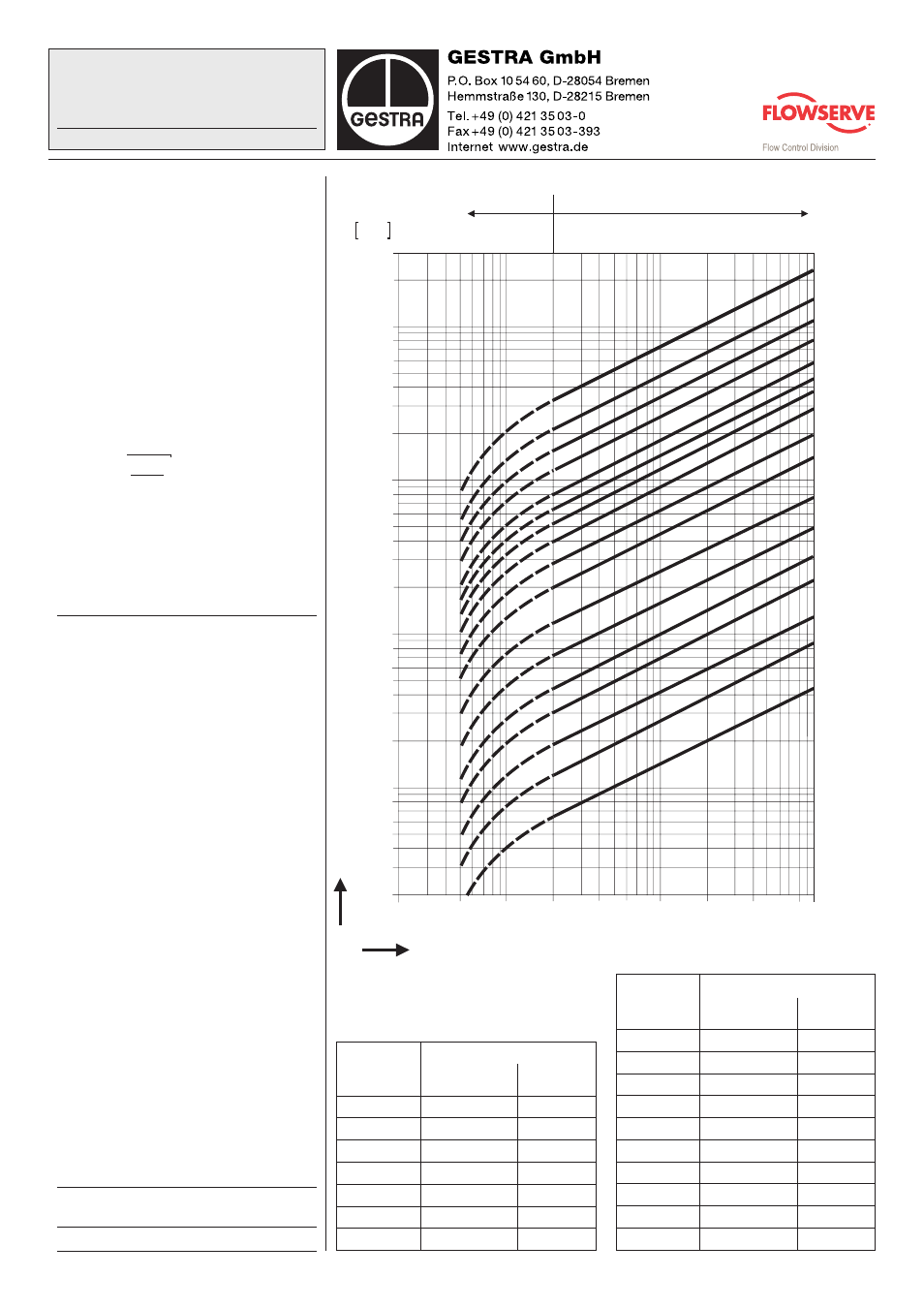
Pressure Drop Chart
The curves given in the chart are valid for
water at 20 °C. To read the pressure drop
for other fluids the equivalent water volume
flowrate must be calculated and used in the
graph.
The values indicated in the chart refer to
valves with horizontal flow. With vertical
flows insignificant deviations occur only
within the range of partial opening.
The chart and flow characteristics are
applicable up to and including PN 40. Higher
PN increase the zeta values and pressure
drops at the same flowrates by approx.
20 %. The k
V
values decrease accordingly.
√
Flow characteristics
Installation in horizontal lines. Fluid: water
at 20 °C.
Nominal size
Dual plate, fully open
DN
Zeta values
K
V
value
[m³/h]
40 + 50
5.1
44.3
65
3.6
89.4
80
4.2
125
100
3.0
230
125
4.2
305
150
3.3
497
200
4.1
793
Nominal size
Dual plate, fully open
DN
Zeta values
K
V
value
[m³/h]
250
3.7
1300
300
3.6
1900
350
3.3
2700
400
3.3
3500
450
3.3
4500
500
3.3
5500
600
3.3
8000
700
3.2
11000
800
2.9
15000
1000
2.9
23500
When selecting valve, please consider
Pressure drop
∆
p [bar]
2
3
4
5
6
8
20
10
30
40
50
60
80
100
200
300
400
500
600
800
1000
2000
3000
4000
5000
6000
8000
10000
20000
30000
DN 1000
DN 800
DN 700
DN 600
DN 500
DN
DN 450
DN 400
DN
DN 350
DN 300
DN 250
DN 200
DN
DN 150
DN 125
DN 100
DN 80
DN 65
DN 40, 50
m /h
3
Partial opening = instable range
Volume flow
V˙
w
Full opening = stable range
0.002
0.005
0.01
0.02
0.04 0.06 0.1
0.2
0.4
0.8 1