Fig. 1: series 1 on-off actuator, air-to-open, Fig. 2: anti-rotation device – Flowserve 2 Series P2 Type User Manual
Page 6
6
Flow Control Division
Kammer Control Valves
in section 1.1.
8.1.2.2
Remove all case retaining screws (20).
8.1.2.3
Remove the upper case half (22).
8.1.2.4
With a suitable press compress the spring set.
8.1.2.5
Secure the actuator stem (10) against rotating with a wrench
across the flats on the stem’s lower part and remove the
lock nut (24) and nut (32).
8.1.2.6
Remove following parts:
washer (1), diaphragm (29), piston (28), spring set (30),
spring plate (27), plate (26) and spacer (25).
8.1.2.7
With a hooked spanner loosen and remove the slotted nut
(9).
8.1.2.8
Remove the guide (4) and upper yoke plate (8).
8.2
ASSEMBLE ACTUATOR
(refer to Figs. 1 and 2)
8.2.1
Actuator action spring-to-close
8.2.1.1
Insert the guide (4) into the lower body half.
8.2.1.2
Replace the upper yoke plate ensuring that the nose in the
lower body rests in the bore of the upper yoke plate (see
fig. 2).
8.2.1.3
Refit the slotted nut (9) and tighten with a hooked
spanner.
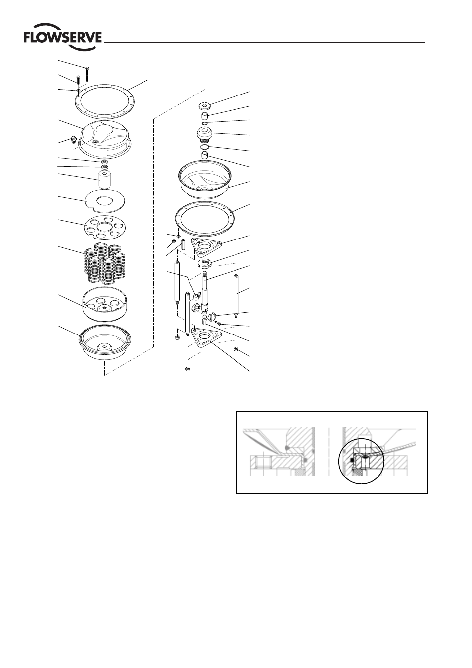
Fig. 1: Series 1 On-Off Actuator, Air-to-Open
1
2
3
4
5
2
6
7
8
9
10
11
12
13
14
15
16
17
18
31
19
21
20
18
22
23
24
32
25
26
27
28
29
7
30
1
Washer
2
Bushing
3
O-Ring 22 x 2
4
Guide
5
O-Ring 32,99 x 2,62
6
Lower body
7
Flange
8
Yoke plate
9
Nut M 38 x 1,5
10
Actuator stem
11
Yoke rod
12
Coupling half
13
Screw
14
Coupling insert
15
Nut
16
Yoke plate
17
Washer, Ø 6,4
18
Nut, M 6
19
Travel indicator, assy.
20
Screw M 6 x 25
21
(De)Compression screw
22
Upper body
23
Vent plug
24
Locknut
25
Spacer
26
Plate
27
Spring plate
28
Piston
29
Diaphragm
30
Spring set
31
Nut
32
Nut
8.2.1.4
Refit the actuator stem (10), washer (1), diaphragm (29),
piston (28), spring set (30), spring plate (27), plate (26)
and spacer (25)
8.2.1.5
Secure the actuator stem (10) from rotating with a wrench
across the flats on the stem’s lower part and retighten the
nut (32) to the torque shown in table 2. Replace locknut
(24) and secure with loctite 221.
8.2.1.6
Replace the upper case half.
8.2.1.7
Insert 3/4 longer (de)compression screws (21) (see table
2) through the upper and lower actuator case halves and
tighten with long nuts (31) in equal measures until the
casing halves contact.
8.2.1.8
Insert and tighten all remaining short case retaining screws
(20) to a torque value of 12 Nm.
Fig. 2: Anti-rotation device