Maintenance, Reassembly, Figure 5: declutchable handwheel – Flowserve Handwheels and Limit Stop User Manual
Page 9
Flowserve Corporation, Valtek Control Products, Tel. USA 801 489 8611
5-9
4. To open, turn the handwheel counter-clockwise.
5. To close, turn the handwheel clockwise.
6. To declutch the handwheel, rotate the handwheel
until there is little or no load on it. Pull the clutch
handle out and index it 90
°
until it seats in the clutch
indicator’s shallow slot.
NOTE: It will be difficult to pull out the clutch
handle if the handwheel mechanism is transmit-
ting torque.
Maintenance
Because the handwheel gearbox is packed with grease,
periodic maintenance is not required; however, periodi-
cally examine the handwheel:
1. Check for bearing and gear wear by pulling on the
handwheel. If it gives more than
1
/
8
-inch in any one
direction, disassemble and inspect the bearings
and gears.
slowly and simultaneously, relieving the remaining
spring compression. The bolts are long enough to
relieve all spring compression prior to removing the
flange (as long as the handwheel is in the full
counter-clockwise position).
WARNING: Make sure handwheel is in full
counter-clockwise position. Otherwise, serious
injury may result when removing the flange
bolts.
5. Lift the handwheel/flange assembly from the actua-
tor. Remove the flange gasket.
6. The actuator may now be disassembled according
to the valve’s or actuator’s maintenance bulletin.
7. If it is necessary to replace the handwheel stem O-
ring, remove handwheel nut and handwheel.
8. Screw the handwheel stem off flange and replace
O-ring. There is no need to replace the bushing.
Reassembly
Refer to Figure 4:
1. Make sure all internal parts are thoroughly cleaned
and lubricated before beginning reassembly. Use
new O-rings and gaskets (O-rings should be lubri-
cated with a silicone lubricant, such as Dow Corning
55 M).
2. Insert new handwheel stem O-ring. Reassemble
handwheel assembly (if disassembled) by screw-
ing the handwheel stem into the flange. Replace the
handwheel, handwheel key and lock nut.
3. Reassemble the actuator using the valve’s or
actuator’s maintenance bulletin.
4. Install a new flange gasket.
5. Position the handwheel/flange assembly on the
actuator.
6. Using new bolt gaskets, install two opposing flange
bolts and tighten evenly to compress spring.
7. Remount and tighten four remaining flange bolts.
DECLUTCHABLE HANDWHEELS
(Rotary Actuators Only)
Operation
The declutchable handwheel used on rotary actuators
can be operated as follows:
1. Set the three-way bypass valve to 'manual' to vent
the air pressure from the actuator.
2. Engage the handwheel mechanism by rotating the
clutch handle 90
°
and allowing it to be fully seated
in the clutch indicator’s deep slot.
3. Rotate the handwheel until the spring loaded clutch
key engages the handwheel gear. At this point the
handwheel mechanism is fully engaged.
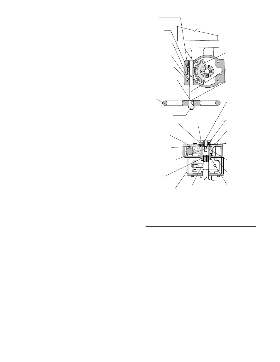
Handwheel Locknut
(Item No. 397-18)
Clutch Indicator
(Item No. 397-20-7)
Cover Plate
(Item No. 397-5)
Clutch Shaft
(Item No. 397-20-1)
Small External
Retaining Ring
(Item No. 397-20-4)
Coupling
(Item No. 397-4)
Transfer Case
(Item No. 204)
Worm
(Item No. 397-10)
Stem Pin
(Item No. 397-14)
Thrust Roller
(Item No. 397-12)
Thrust Race
(Item No. 397-13)
Stem Bushing
(Item No. 397-7)
Handwheel Key
(Item No. 397-17)
Handwheel
(Item No. 397-1)
Clutch Handle
(Item No. 397-1)
Handwheel Gear
(Item No. 397-3)
Handwheel Stem
(Item No. 397-2)
External
Retaining Ring
(Item No. 397-16)vva
Large External
Retaining Ring
(Item No. 397-20-3)
Screw
(Item No. 397-20-5)
Cover Plate Bolt
(Item No. 397-8)
Compression
Spring
(Item No. 397-20-2)
Clutch Key
(Item No. 397-6)
Housing
(Item No. 397-9)
Flanged
Bushing
(Item No. 397-15)
Shaft
(Item No. 50)
Figure 5: Declutchable Handwheel
NOTE: Item numbers shown above correspond directly to the valve’s
bill of material. Refer to the bill of material for specific part numbers.