4 setting the close limit switch – Flowserve L120-85 Actuator User Manual
Page 18
position point and turn the Intermediate Open Shaft in a
CCW
direction until the Rotor Cam rotates 90° to
make an OPEN contact (OPEN limit trip point = Rotor Cam
in a vertical orientation to make an OPEN contact). Once
you have reached the full OPEN position point, rotate the
Intermediate Shaft slowly in the CW
direction until the
Rotor just trips again.
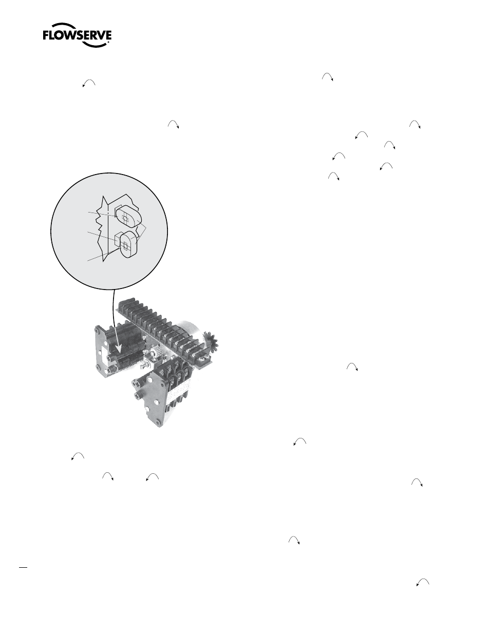
Figure 10: Limit Switch OPEN/CLOSED Rotor Cam orientation
OPEN
Contact
CLOSED
Contact
Contact
Plunger
Rotor
Cams
8. Before operating the actuator, depress and turn the Clutch Screw
CCW
one-quarter turn to the spring release position.
Insert a screwdriver into each of the Intermediate Shafts and
“rock” them CW
and CCW
a few times to ensure all
the gearing is seated well.
4.5.4 Setting the CLOSE Limit Switch
1. De-engerize electrical circuit to the actuator.
2. Open Electrical Compartment Cover (piece 200-1).
3. Put the actuator into MANUAL operation by moving the Declutch
Lever in the direction of the arrow on the lever until the Declutch
Lever locks in place.
4. Turn the Handwheel CW
to move the valve to the full
CLOSED position. While turning the Handwheel, note the direc-
tion of the Intermediate Shaft that corresponds to the Closed
Rotor Group.
NOTE: Most applications require turning the Handwheel CW
to
obtain the full CLOSE position and CCW
to obtain full OPEN
position. The actuator Drive Sleeve rotates in a CW
direction
to the CLOSE position and CCW
to the OPEN position. The
Limit Switch Intermediate Shafts rotate in a CCW
direction
to the CLOSE position and CW
to the OPEN position. If your
application is configured differently, keep in mind that the descrip-
tions in this manual will describe rotation directions opposite of your
application.
5. Once the valve is fully CLOSED, turn the Handwheel back toward
OPEN approximately one full turn. This will allow for coasting
during motor operation.
a
CAUTION: Do not operate the actuator when the Clutch
Screw is in a fully depressed position; loss of the
contact setting will occur and the Setting Rod will be
damaged.
a
CAUTION: For highly geared actuators, one turn of
the handwheel may not be sufficient to allow for coast
of moving parts. Refer to valve manufacturer setting
requirements in these cases.
6. Push in Clutch Screw and turn CW
one-quarter turn to latch
in a depressed position. See Figure 9 for Limit Switch nomencla-
ture.
7. Limit Switch Rotor Cams
A. If your Limit Switch Rotor Cams did not trip at the full
CLOSE position point, turn the Intermediate Close Shaft
in a CCW
direction until the Close Limit Rotor Cam
rotates 90° to make an OPEN contact (CLOSE limit trip
point = Rotor Cam in a vertical orientation to make an OPEN
contact). Once you have reached the full CLOSED position
point, rotate the Intermediate Shaft slowly in the CW
direction until the Rotor just trips again.
B. If your Limit Switch Rotor Cams did trip before reaching
the full CLOSE position point, leave the valve at the full
CLOSE position point and turn the Intermediate Close Shaft
in a CW
direction until the Close Limit Rotor Cam
rotates 90° to make an OPEN contact (CLOSE limit trip
point = Rotor Cam in a vertical orientation to make an OPEN
contact). Once you have reached the full CLOSE position
point, rotate the Intermediate Shaft slowly in the CCW
direction until the Rotor just trips again.
Limitorque L120-85 Installation, Operation and Maintenance FCD LMENIM1202-00 – 11/05
18