Flowserve 5000 Positioner Automax Valve Automation Systems User Manual
Page 4
©
2011, Flowserve Corporation, Printed in USA
FCD AXAIM0030- 01 (LMR0004-0) (AUTO-30) 03/ 11
3-Position Control/Dribble Control
SR Limit Switch Method
Automax Valve Automation Systems
Installation, Operation and Maintenance Instructions
Flowserve Corporation
1350 N. Mountain Springs Parkway
1978 Foreman Dr.
Flow Control Division
Springville, Utah 84663-3004
Cookeville, TN 38501
www.flowserve.com
Phone: 801 489 2233
Phone: 931 432 4021
Class I, Division 2, Applications must be installed as specified in NEC Section 501-4 when barriers are not used.
(Refer to ANSI/ISA RP12.6 for guidance on installation).
Electrical Specifications:
Field Installation:
All input options can be added/changed
in the field without removing positioner cover. Figures 3
and 4 (5100 and 5200/5600 respectively) show mounting
information and location of terminal connections.
Caution:
If I/P Module is installed in explosive atmosphere,
disconnect power prior to removing cover to avoid
personal injury.
1. Remove supply pressure and input signal connection.
2. Remove old I/P Module or pneumatic manifold and
associated hardware.
3. Following applicable figure, install new I/P Module and
associated hardware. Be sure o-rings are in place.
4. Make electrical and pneumatic connections. Do not use
Teflon tape on supply connection fitting. Use only a
liquid or paste non-hardening pipe sealant on
the threads.
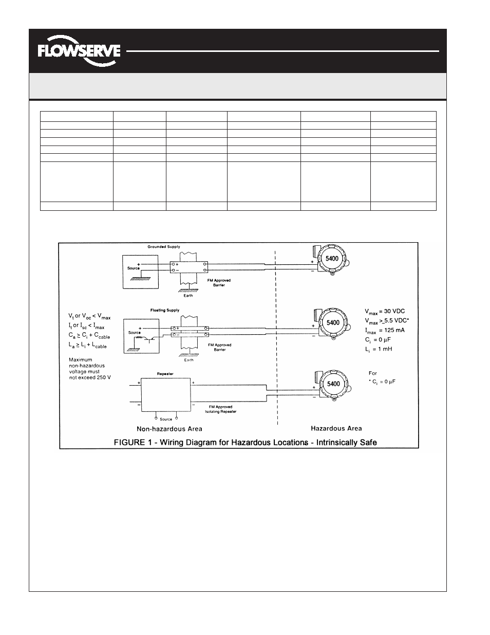
5. For intrinsically safe applications (Model 5400 only)
refer to Figure 1 for barrier information and schematics.
6. All I/P Modules are factory calibrated and should not
require adjustment. However, it is recommended that
calibration be checked (see “I/P Module Calibration”).
7. Install cover.
Page 4 of 8
Parameter
Model 5100
Model 5200
Model 5300
Model 5400
Model 5600
Max. Voltage VDC
30
30
28
30
28
Min. Voltage VDC
6
5.5
5.5
5.5
5.5
Max. Current (mA)
50
125
93.3
125
93.3
C (Micro Farad)
1
1
1
1
1
L (Mili Henry)
1
1
1
1
1
Hazardous Locations
Exp. Proof
Exp. Proof
Intrinsically Safe
Intrinsically Safe
CL l,ll, Div 1
EEx d llB+H2
CL l,ll Div 1
EEx ia llC T4
Non-incendive
T6-40 to +40C
Groups B-G
CL l, Div 2
T5-40 to +75C
Groups A-D
T4-40 to 110C
Agency Approval
FM/CSA
SCS
FM/CSA
SCS