Wiring, Worcester controls – Flowserve 90 Series Solenoid Block Kit User Manual
Page 4
Flow Control Division
Worcester Controls
4
Solenoid Block Kit for Series 90 Modular Accessory System
WCAIM2043
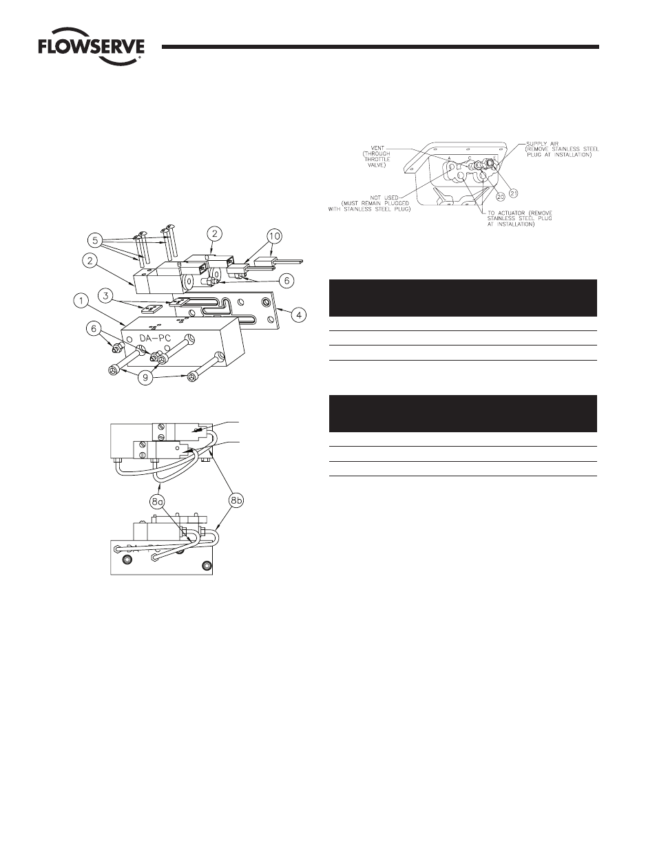
2. Lightly lubricate and install the four #10-32 air fittings (item 6)
as shown, and tighten. Assemble the two lengths of
1
/
16
" I.D.
tubing (item 8a – 3" and item 8b – 6") between the solenoid
valve and solenoid block after the air fittings are in place. The
tubing is difficult to remove and will not allow the fittings to
be tightened once installed.
3. Insert the three #10-32 x 1
1
/
2
" socket head screws (item 9)
through the solenoid block from the side marked “DA-PC.”
Position the solenoid gasket (item 4) on these screws.
NOTE: See solenoid valve identification table.
4. Attach the solenoid block and gasket to the angled inside wall
of the M.A.S. base using the three #10-32 x 1
1
/
2
" screws.
5. Install the Exhaust Throttle Valve (item 20) into port “C” as
shown in the figure below. Thread Exhaust Nut (item 21) onto
the fitting. (Throttle valve is shipped from the factory fully
open.) Pipe thread sealant can be applied sparingly if desired.
Fluoropolymer tape thread sealant is not to be used.
6. The air connection bosses on the outside wall of the M.A.S.
base function as indicated in the figure below.
Solenoid Valve Identification Table: Spring-Return
Solenoid A
Solenoid B
Identification No.
Identification No.
Voltage
(Normally Open)
(Normally Closed)
120 VAC
D1X268P
D1X268
12 VDC
D1X270P
D1X270
24 VDC
D1X271P
D1X271
Solenoid Valve Identification Table: Double-Acting
Solenoid A
Solenoid B
Identification No.
Identification No.
Voltage
(Normally Open)
(Normally Closed)
120 VAC
D1X268
D1X268P
12 VDC
D1X270
D1X270P
24 VDC
D1X271
D1X271P
2. WIRING
NOTE: All wiring is to be run smoothly and neatly and away from any
rotating parts and away from the base/cover flange joint, using wire
tires, if necessary. Use caution to avoid pinching wires and/or
solenoid rectifiers between the base and cover flanges.
All wiring to terminal strip shall be inserted only to mid-point of
terminal strip.
Grounding wires should be connected to green-colored grounding
screw on M.A.S. base.
a. SINGLE-ACTING AND DOUBLE-ACTING ON/OFF TYPE
1. 120 VAC OPERATION – Connect one of the black wires from the
lead wire/connector to the “internal” side of terminal A (neutral
AC power) on the side terminal strip. Connect the other black
wire to the “internal” side of terminal B (hot AC power).
To assure proper operation of the low-current AC solenoid
valves used in the M.A.S. with DCS and PLC controllers, a 1
mfd capacitor is placed across the incoming 120 VAC
power supply.
SOL. A
SOL. B