Worcester controls – Flowserve I90 Series Intrinsically Safe Modular Accessory System User Manual
Page 9
2. WIRING
NOTE: All wiring is to be run smoothly and neatly and away
from any rotating parts and away from the base/cover flange
joint, using wire ties if necessary. Use caution to avoid
pinching wires between the base and cover flanges.
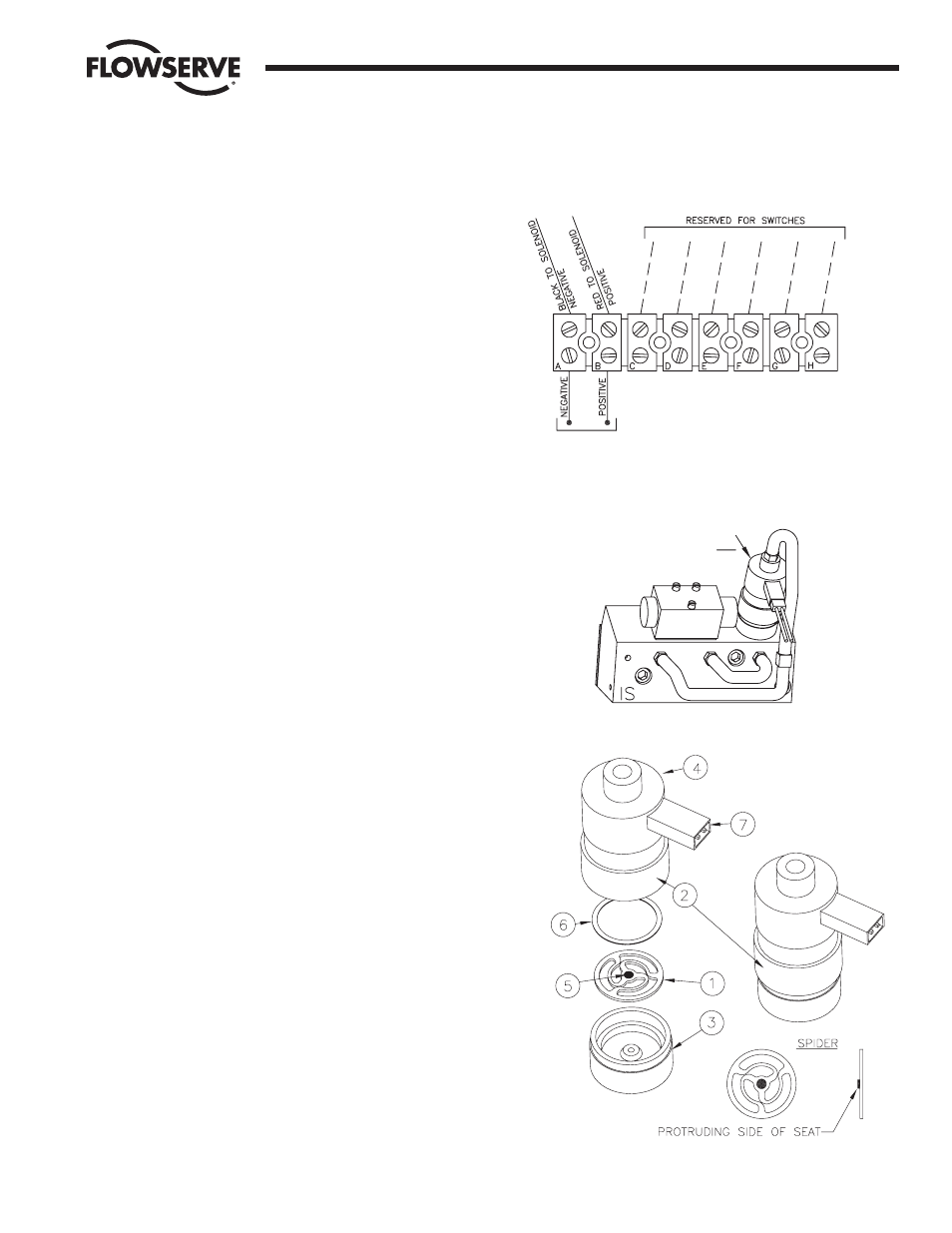
Connect the solenoid lead wires to the side terminal strip as
shown in the wiring diagram to the right. NOTE: All wiring
should be inserted only to mid-point of terminal strip. Refer to
section III.B for more details regarding wiring of intrinsically
safe systems, barrier selection, etc.
3. OPERATION
a. Solenoid block is ported such that when not energized,
the actuator will be in its closed (full-clockwise) position.
b. Energizing solenoid “A” will provide air to the actuator to
open (full-counterclockwise).
4. REPAIR OF SOLENOID VALVE (Refer to Figure 15)
The intrinsically safe solenoid valves used in the M.A.S. are
very reliable. Due to their construction, each is “hand-tuned”
by the manufacturer to very close tolerances for optimum
performance. Occasionally, a valve may be operated in a
system with moist or lubricated air that causes the rubber
seat in the valve to swell slightly. If this happens, the valve
may operate slowly, irregularly, or not at all. This situation can
be repaired in the following manner:
a. Obtain a new “spider” element (item 1). Contact Clippard
Instrument Laboratory at (513) 521-4261 for information
on a local distributor.
b. Loosen the knurled retaining ring (item 2) and separate
the solenoid into its two sections (items 3 and 4).
c. Remove and replace the “spider” (item 1). Be certain that
the protruding side of the rubber seat (item 5) faces
down, touching the lower section of the solenoid (item 3),
and that the shim (item 6) is above the “spider” as
shown.
d. Reassemble the two sections of the valve, orient the
electrical connector (item 7) to a convenient location, and
tighten the retaining ring.
5. TROUBLESHOOTING
See table on following page.
C. SWITCH OPTIONS
A mechanical switch option is available in the Series I90 Modular
Accessory System. The switches can be used to provide actuator
position indication or to control other equipment.
The option always available (regardless of other options) is:
M2 – Two Single-Pole, Double-Throw mechanical switches
An “Adjustment Plate” is used to mount the single-pole
mechanical switches to the baseplate. Mechanical switches are
mounted to the adjustment plate and set to a middle position —
Flow Control Division
Worcester Controls
WCAIM2033
Intrinsically Safe Modular Accessory System (Series I90)
9
SINGLE– OR DOUBLE-ACTING ACTUATORS
INTERNAL
EXTERNAL
Customer-Supplied
Wiring
SOLENOID "A"
SUPPLY VOLTAGE
15.5 VDC
NOMINAL
(CONNECT THROUGH
APPROPRIATE BARRIER)
Figure 15