Iii. maintenance and troubleshooting, Iv. spare parts, V. electrical requirements – Flowserve 36 Series Electric Actuator User Manual
Page 3
Flow Control
Worcester Actuation Systems
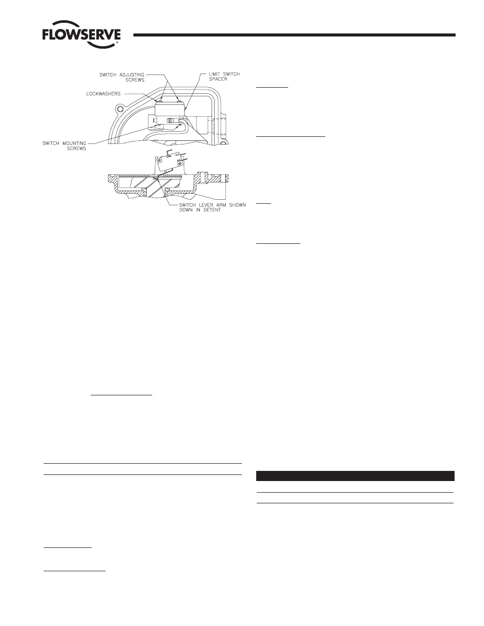
change the above details. When the switch arm is up, the valve is
closed; when the switch arm is down, the valve is open.
D. Proper Alignment of Switch:
The limit switch is adjusted and set at the factory for proper 90°
operation. Verify switch setting prior to operation. In the event
that the switch is not at the desired setting, adjust as follows:
The limit switch of the 36 Actuator can be adjusted in two
directions; up-and-down and side-to-side (refer to Fig. 2).
To adjust the limit switch, loosen the adjusting screws on the
casting’s switch support. Once these screws are loosened, the
limit switch can move up, down and sideways a total of
3
/
8
inches.
Moving the switch horizontally causes both stop points to shift.
Moving the switch vertically changes the 90°/90° rotation.
Adjust the switch vertically for uniform 90° cycles, then shift it
horizontally to set the stop points.
Secure the switch fastening screws when proper valve indexing is
verified thru one complete rotation of the valve (360°).
The actuator is now ready for operation.
III. MAINTENANCE and
TROUBLESHOOTING
a WARNING: Disconnect power during cover removal.
The Series 36 Electric Actuator requires no regular maintenance. The
actuator utilizes a permanently lubricated gear train. No additional
lubrication is necessary.
Should the actuator fail to operate, the following are hints for trouble-
shooting.
Electrical Supply: Be sure the actuator is supplied with the correct
voltage.
Electrical Connections: Does the wiring conform to the wiring diagram?
Motor Module:
AC Motors: If the motor winding is short-circuited, or if the
thermostat has opened the winding, the unit will not operate. If the
motor is hot, allow it to cool down so that the stator is at room
temperature. Apply voltage to motor. If motor still fails to operate,
replace the entire motor module.
Motor Bearing Alignment: The actuator motor uses self-aligning
bearings. During shipment, the bearing may become misaligned, so the
actuator will not operate. Tapping the motor stator (lamination around
top bearing bracket with a plastic hammer or screwdriver handle) while
it is energized will realign the bearings. The unit will then develop full
output. To perform this adjustment, reenergize unit with cover off. If
rotor hums, but does not turn, tap stator lightly as described.
Valve: The problem may lie with the valve instead of with the actuator.
Check the operation of the valve by removing the actuator and
operating the valve manually. Measure valve torque and compare to
actuator torque.
Optional Switch: If an extra switch is used, its contact arm must lead
(be shorter than) the contact arm of the actuator operating switch,
i.e., the auxilliary switch must trip before the positioning switch.
Check to ensure clearance between the extra limit switch lever arm
and the retaining shroud. If they are touching, loosen the motor
mounting screws and move retaining shroud enough to clear the
switch lever arm.
IV. SPARE PARTS
The following are recommended spare parts which should be kept on
hand for Series 36 Electric Actuators:
1 Spare Limit Switch (Used for Valve Control Only)
NOTE: This spare limit switch can be ordered by part number and
differs from the (optional) extra limit switch.
When ordering any spare parts, please specify actuator size and
voltage.
V. ELECTRICAL REQUIREMENTS
The following table represents current draw in amperes at the various
voltages and rated stall torque for each motor:
Voltage (AC)
1036 (5 sec.)
2036 (5 sec.)
120
2.3
3.8
240
1.0
1.7
The duty cycle for all motors used in the Series 36 Actuator is 20%
(at 70°F).
Figure 2