Flowserve APS2 Module User Manual
Page 2
Flowserve Corporation
765 South 100 East
Phone: 801 373 3028
Flow Control Division
Provo, Utah 84606-6160
Facsimile: 801 489 2228
Automation Business Unit
www.flowserve.com
Email: [email protected]
© 2001, Flowserve Corporation, Provo, Utah
Automax Valve Automation Systems
Installation, Operation and Maintenance Instructions
LMR0016-0 (AUTO-16) 11/01
Page 2 of 2
Maintenance Instructions
Trouble Shooting the APS2
Actuator will not cycle.
1. Check for proper orientation of APS2.
2. Check for pinched diaphragm.
3. Check for plugged exhaust port.
Air leaks through breather exhaust when actuator
is held open.
1. Check for pinched diaphragm.
2. Check for diaphragm wear. Diaphragm should be
flexible with no tears.
3. Increase supply air pressure.
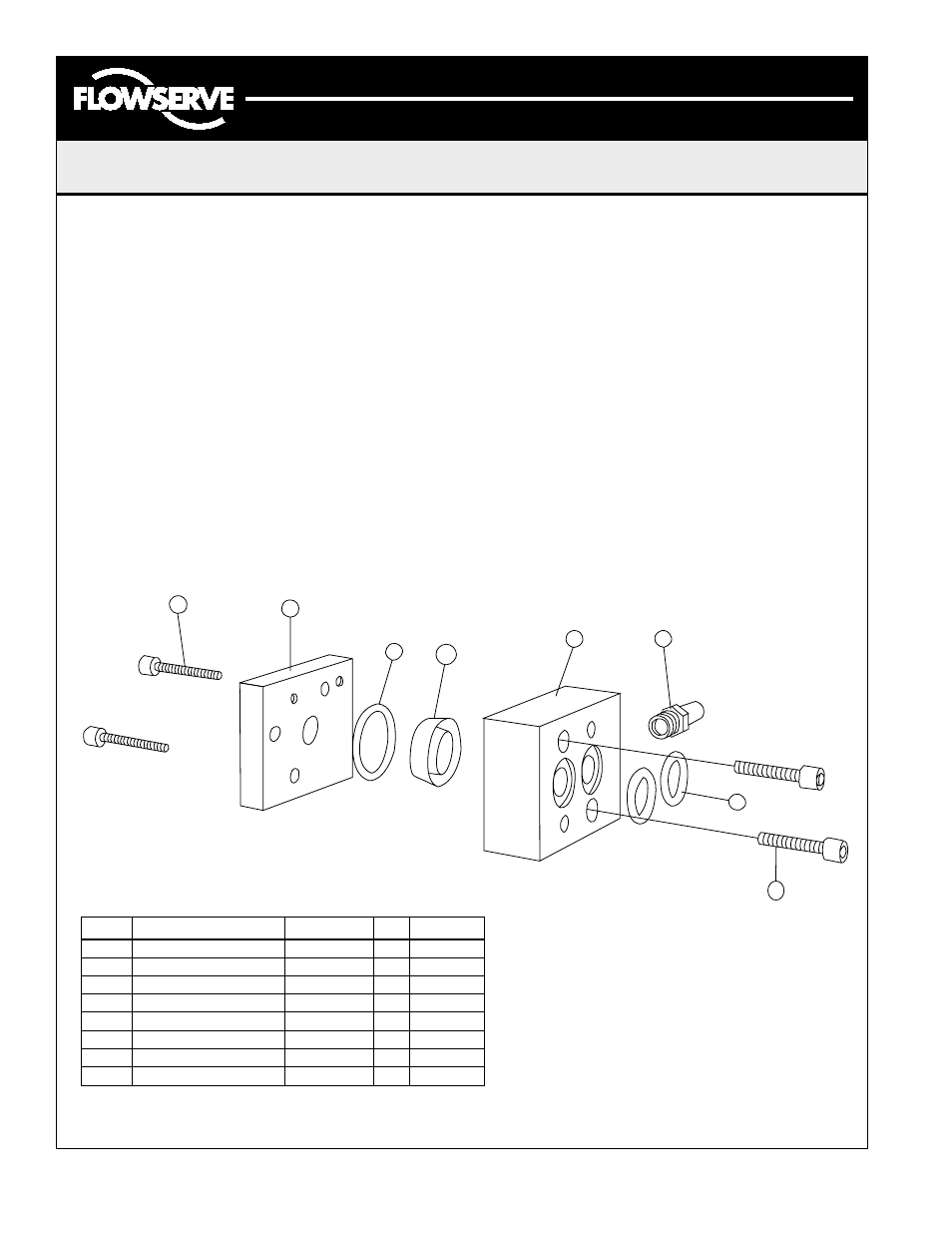
Assembly
1. Hold upper housing (2) with actuator ports side
down. Place large o-ring (4) into o-ring groove of
lower housing.
2. Place diaphragm (3) into center of bore of lower
housing. (See exploded view for diaphragm
orientation.)
3. Aligning pin in upper housing (1), place upper
housing on lower housing.
4. Fasten housing together with M5–.8 x 25 mm
SHCS (6) from lower housing side.
5. Attach breather vent (8) to lower housing, using a
sealant.
6. Place small o-rings (5) into o-ring grooves of
lower housing.
7. Mount to actuator with M5–.8 x 35mm SHCS (7).
Disassembly
Disassembly is reverse of assembly.
Standard Components
Part #
Description
Materials
Qty.
P/N
1
Upper Housing
Aluminum
1
M610064
2
Lower Housing
Aluminum
1
M610063
3
Diaphragm
Polyurethane
1
4
O-Ring
Nitrile
1
106073
5
O-Ring
Nitrile
2
105775
6
M5––.8 x 25mm SHCS
Steel
2
7
M5—.8 x 35mm SHCS
Steel
2
106075
8
Breather Vent
Bronze
1
106200
6
5
8
2
3
4
1
7