Worcester controls – Flowserve 93 Series PULSAIR III User Manual
Page 6
6
Series 93 PULSAIR III Digital Electronic Positioner Installation, Operation and Maintenance
19860-C
Flow Control Division
Worcester Controls
14. Press the FUNC button once and the display should read
‘Transm’ over ‘Transm low’.
15. Press the FUNC button once and display should read ‘Transm
low’ over ‘LO=4.0 mA’.
16. Press the UP or DOWN button as necessary to adjust the output
signal to read 4.0 mA, or as close to 4.0 as is possible.
17. Press the OK button to accept the setting. The display should
read ‘Transm low’ over ‘UPDATED’ for a brief moment.
18. Press ESC and display should read ‘Transm’ over ‘Transm low’.
19. Press DOWN once and display should read ‘transm’ over
‘Transm hi’.
20. Press FUNC button once and the display should read ‘Transm hi’
over ‘HI=20.0 mA’.
21. Press the UP or DOWN button as necessary to adjust the output
signal to read 20.0 mA, or as close to 20.0 as is possible.
22. Press the OK button to accept the setting. The display should
read ‘Transm hi’ over ‘UPDATED’ for a brief moment.
23. Press the ESC button for 2-3 seconds and the display will return
to the ‘FULL MENU’ over ‘MAN/AUTO’ screen.
24. Disconnect the calibration ammeter from terminal positions 11
and 12, and attach your readout leads to terminal position 11
(positive) and 12 (negative).
Limit (M2) and Proximity (R2) Switch Cam Adjustment
(for L93W Positioner only)
1. Connect an ohmmeter to terminal position 3 (switch 1 -
normally open) and terminal position 5 (switch 1 - common).
2. Input a 4.2 mA signal so that the positioner is in the clockwise
position.
3. Using a screwdriver or similar tool, use the notch on the lower
cam and rotate the cam counter-clockwise away from the
switch and then clockwise until switch 1 closes. The ohmmeter
indication changes from infinite to a low reading that indicates
continuity through the switch.
4. Input a 19.8 mA signal so that the positioner is in the counter-
clockwise position.
5. Connect the ohmmeter leads to terminal position 6 (switch 2 -
normally open), and terminal position 8 (switch 2 - common).
6. Using a screwdriver or similar tool, use the notch on the upper
cam and rotate the cam clockwise away from the switch, and
then counter-clockwise as necessary until switch 2 closes. The
ohmmeter indication changes from infinite to a low reading that
indicates continuity through the switch.
7. Tighten the 2 mounting screws on the cam assembly to lock the
cam positions in place.
8. Adjust the input signal to 15 mA, and return to 20 mA to verify
that the cam contacts or trips the switch, and the ohm reading
changes from infinite to a low reading.
9. Remove the ohmmeter leads from terminal positions 6 and 8,
and attach them to terminal positions 3 and 5.
10. Adjust the input signal to 4 mA and verify that the cam contacts
or trips the switch and the ohm reading changes from infinite to
a low reading.
11. If the ohm reading does not change, and continues to show an
infinite reading, loosen the cam assembly mounting screws and
adjust the cam as necessary.
12. Repeat the adjustment and set procedure until you can supply a
4 mA and a 20 mA signal and have the switches close.
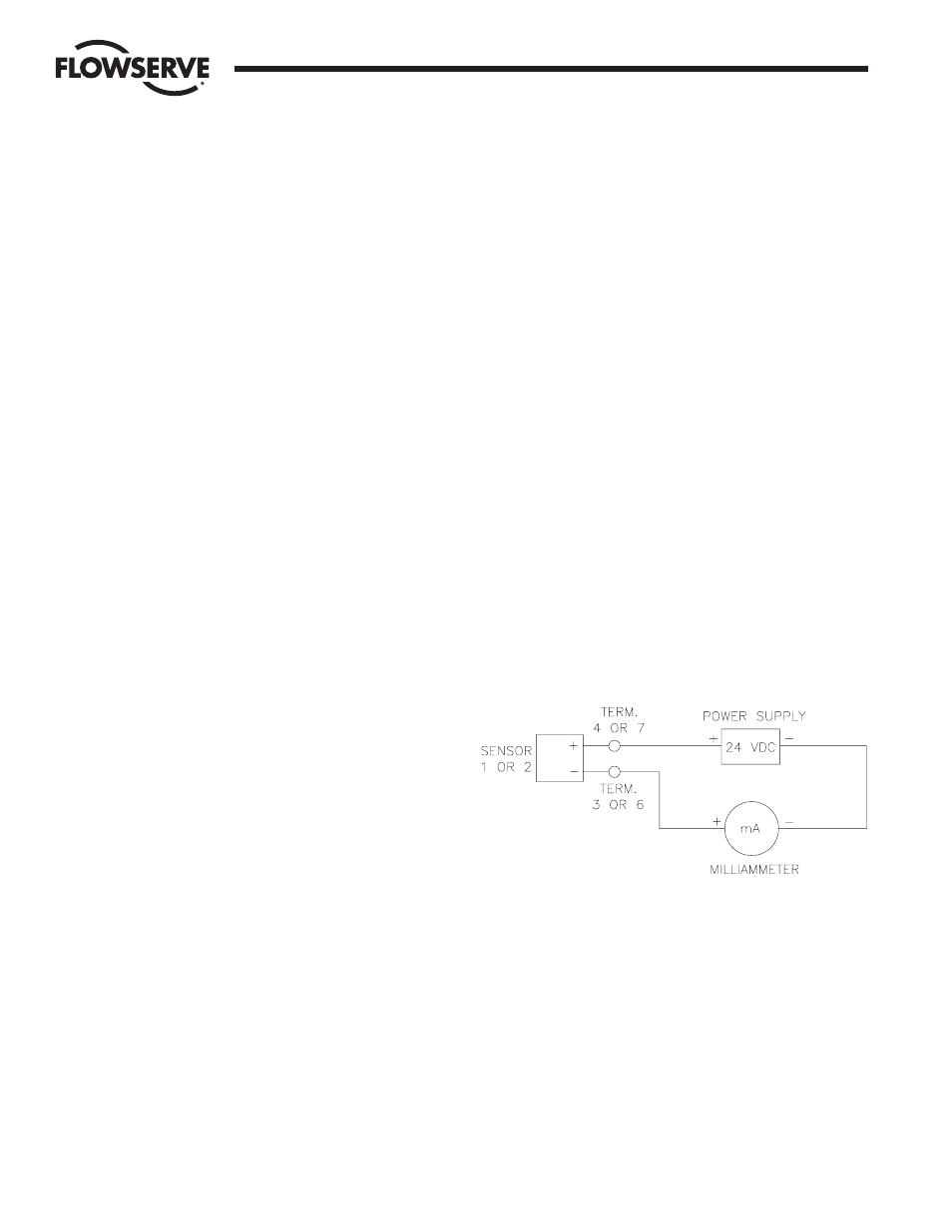
Namur Sensor (P2) Cam Adjustment (for L93W Positioner only)
Refer to diagram below:
1. Connect a milliammeter positive lead to terminal position 3
(sensor 1 - negative), and a 24 VDC power supply positive lead
to terminal position 4 (sensor 1 - positive). Connect the
millammeter negative lead to the 24 VDC power supply negative
terminal.
2. Input a 4.2 mA signal so that the positioner is in the clockwise
position.
3. Using a screwdriver or similar tool, use the notch on the lower
cam and rotate the cam counter-clockwise away from the sensor