Device initialization, Adjustment of switch cams, Valve position monitoring and reporting – Flowserve AS-I Bus Card for BUSwitch User Manual
Page 3
AXAIM025-00 (AUTO-87) 7/01
Page 3 of 4
©2001, Flowserve Corporation, Provo, UT
Flowserve
Corporation
765
South
100
East
Phone:
801
373
3028
Flow
Control
Division
Provo,
Utah
84606
Facsimile:
801
489
2228
Automation
Business
Unit www.flowserve.com
Email:
Automax Valve Automation Systems
Installation, Operation and Maintenance Instructions
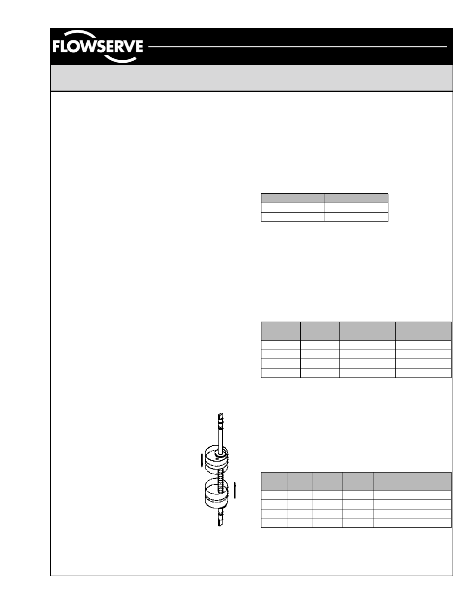
Figure 4
Special Notes on AS-I cabling
Minimum voltage requirement for the BUSwitch™ is
29.5 VDC supply. The output voltage of the fieldbus
power supply, the current drawn and the electrical
characteristics of the data cable determine the
maximum distance that a particular segment can
span. With data cable that conforms to the AS-I
cable specified in section 5.5.3 of AS-I specification
V2.0 distances of 100 m are guaranteed. If a
shielded cable is used, connect the shield to ground
at one point only. Multiple grounds can lead to
ground loops which can impair the proper operation
of the segment. For this reason, a shield connection
has not been provided inside the BUSwitch™
housing. Radio frequency grounding at multiple
points through the use of capacitors is not allowed
by the AS-I protocols. For a more thorough
treatment of data cable wiring and aspects of
installation refer to the AS-I specification V 2.0.
Device Initialization
Each new device that is connected to the AS-I
network is recognized within 10ms. Devices are
immediately ready for use when an address is
assigned. Make sure each device to be connected
to a bus segment has a unique address prior to
starting configuration software. This will ensure that
each device is recognized by the system. Duplicate
addresses can result in devices not being
recognized.
Adjustment of Switch Cams
1. Loosen five captive cover screws and
remove lid, turning slightly while lifting.
2. Place the actuator in the clock-wise
(CW) position and connect to the AS-
I bus segment.
3. Push down on the top cam until it
clears the splined coupler, rotating
clockwise until the CW LED is
illuminated (figure 4).
4. Release the cam and insure that it
fully engages the spline.
5. Place the actuator in the counter-
clockwise (CCW) position.
6. Pull up on the lower cam until it
clears its splined coupler, rotating
counter-clockwise until the CCW LED is
illuminated (figure 4).
Pneumatic Actuator Operation – Single
Coil, Fail Open or Fail Closed
For operation requiring a consistent fail position
(either open or closed), One output is used as
shown in the Single Coil Truth Table. To reverse the
actuator fail mode for double acting actuators,
reverse actuator ports. To reverse spring-return
actuators, actuator modification is necessary.
Single Coil Truth Table
Output 1
OPEN/CLOSE
0 De-energized
1 Energized
Pneumatic Actuator Operation – Dual
Coil, Fail in Last Position
Dual Coil Operation uses both output 1 and output 2
as shown in the Dual Coil Truth Table. For valve
movement to take place, the Output parameters
must take on opposite values as shown below.
Dual Coil Truth Table
Output 1
Output 2
OPEN
CLOSE
0
0
No Change
No Change
1 0
Energized
De-energized
1
1
No Change
No Change
0 1
De-energized
Energized
Valve Position Monitoring and Reporting
The BUSwitch™ monitors the status of two limit
switches. SW1 is the upper switch and is set to trip
when the valve reaches the closed position. SW2 is
the lower switch and is set to trip when the valve is
open.
Truth Table for Switch Values
SW1 SW2
Input
1
Input
2
Meaning
A A 1 1 Improper
switch
adj.
A
O
1
0
Actuator CLOSED
O A 0 1 Actuator
OPENED
O
O
0
0
Actuator is moving
A = Activated or Tripped, O = Open or Not Tripped