Wiring diagram, Fig. 2 fig.1 – Flowserve NRS 1-40 User Manual
Page 3
Advertising
3
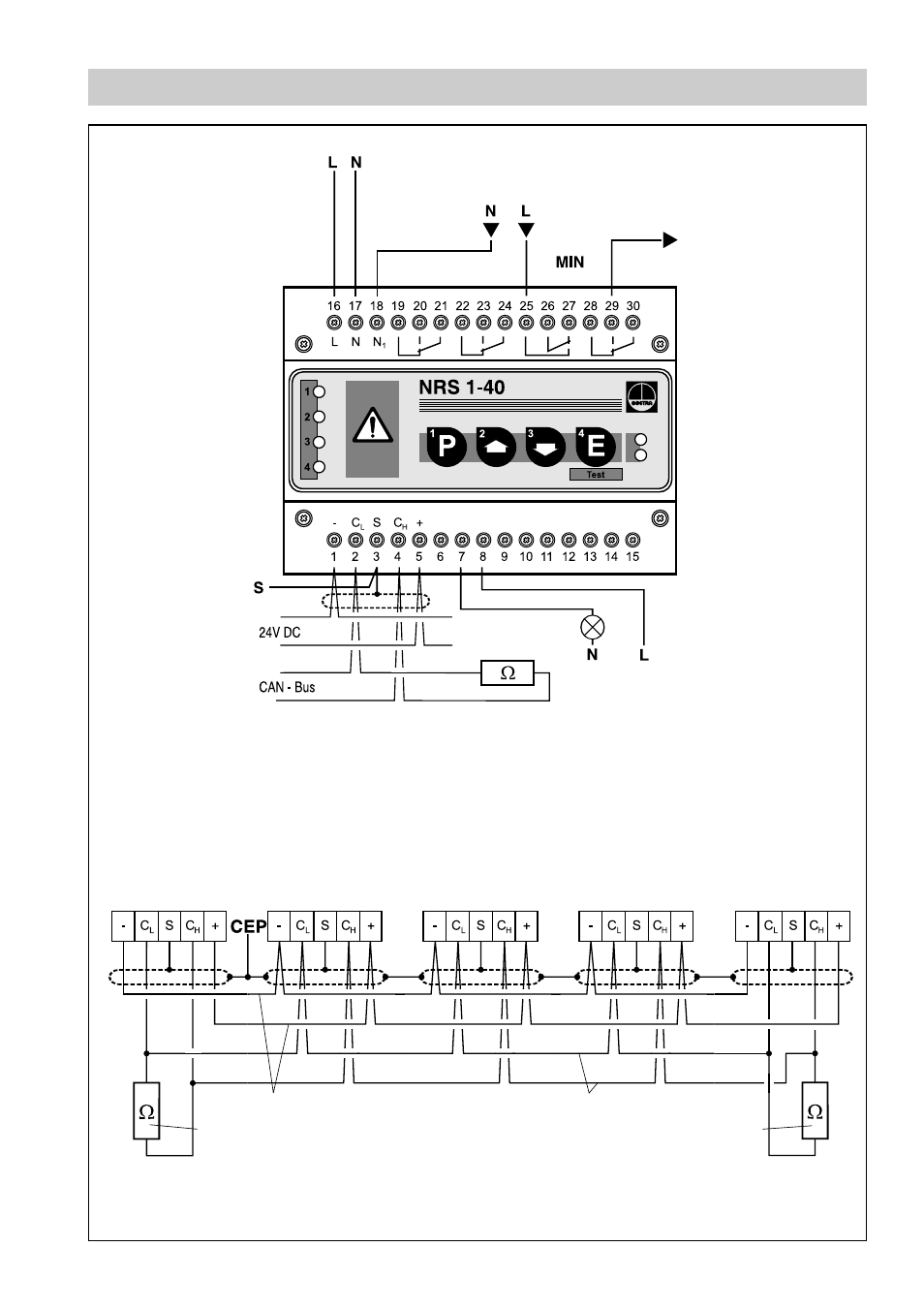
Wiring Diagram
Fig. 2
Fig.1
Control terminal
URB 1
Switching
controller
NRS 1-40
Controller
. . .
Level electrode
NRG 16-40
Terminating resistor
120
Ω
Voltage supply
CAN data line
Terminating resistor
120
Ω
Protection circuit
– uninterrupted –
Twisted pair cable
Twisted pair cable
Photo-Mos output
24 V- 230 V AC/DC, 100 mA
Instantaneous LW alarm,
clocked malfunction signal
Further safety
equipment
Note:
The NRS 1-40 is
the first equipment
of the safety chain.
All relay contacts are
internally linked.
Level sensor
NRG . . .
Terminating resistor
120
Ω
Advertising