Chapter 2 installation instructions, Front panel connector: fp1 – Foxconn K8S760MG-6ELRS User Manual
Page 27
20
Chapter 2 Installation Instructions
K8S760MG Series User Manual
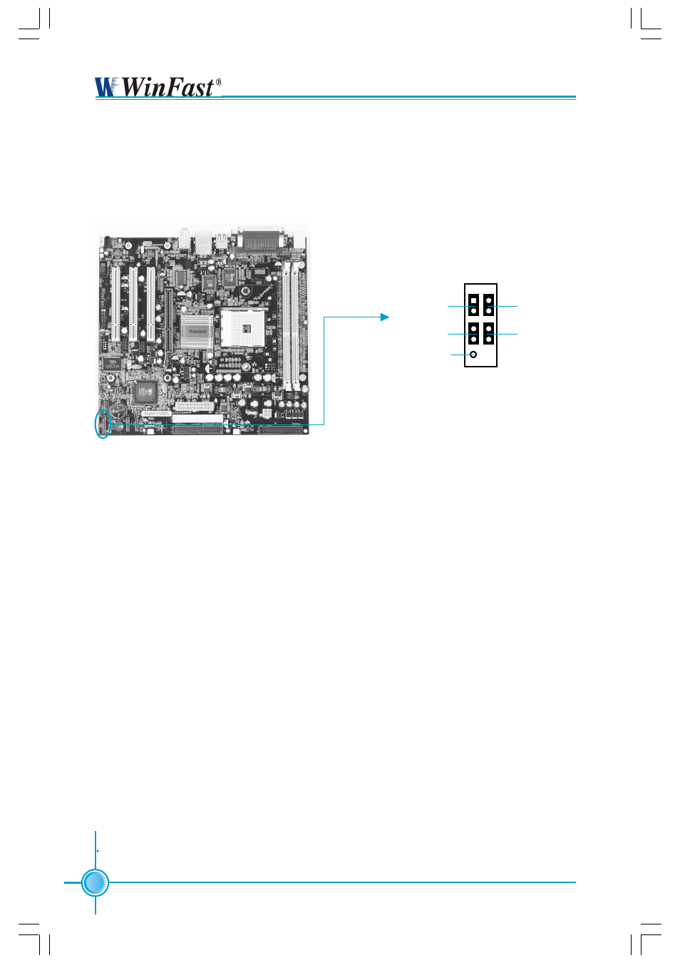
Front Panel Connector: FP1
This motherboard includes one connector for connecting the front panel switch
and LED indicator.
Hard Disk LED Connector (HD-LED)
The connector connects to the case’s IDE indicator LED indicating the activity
status of hard disks.
Reset Switch (RESET-SW)
Attach the connector to the Reset switch on the front panel of the case; the
system will restart when the switch is pressed.
Power LED Connector (PWR-LED)
Attach the connector to the power LED on the front panel of the case. The Power
LED indicates the system’s status. When the system is in S0 status, the LED is
on. When the system is in S1 status, the LED is blink. When the system is in S3,
S4, S5 status, the LED is off.
Power Switch Connector (PWR-SW)
Attach the connector to the power button on the front panel of the case. Pushing
this switch allows the system to be turned on and off rather than using the
power supply button.
NC
HD-LED
RESET-SW
P W R - L E D
P W R - S W
+
-
+ -
9 10
1 2
FP
FP1
!
K8S760MG-WINFAST-V1.0 .p65
2004-9-14, 8:41
20