Specifications, Unit type no. 13380-xxx, Impedance – GAI-Tronics 13380-xxx Series 13380-xxx Series Loudspeakers Instruction and Service Manual User Manual
Page 3: Max. operating temperature / code at +55ºc ambient, Max. operating temperature / code at +40ºc ambient, Mounting, Wiring installation, Instruction & service manual
__________________________________________________________________________________________________________________
GAI-Tronics
400 E. Wyomissing Ave. Mohnton, PA USA [email protected] Tel: 800-492-1212
Document No. IS4211-GAI-TRON Issue: A 24-06-14 www.gai-tronics.com Fax: 610-796-5954
Sheet
3 of 4
INSTRUCTION & SERVICE MANUAL
13380-XXX 15W LOUDSPEAKERS
For Use In Hazardous Locations
15
Watt
Loudspeaker
70V or 100V Line Transformer
with 15W, 7.5W, 3W and 1W tapings
8 ohm or 16 ohm
Type 4 / 4X / 13
Operating Temperature Range
−20ºC to +55ºC
7KA1
Unit Type No.
13380-XXX
Impedance:
8 ohm or 16 ohm
70V Line or 100V Line
Max. Operating Temperature / Code at +55ºC Ambient
Hazardous Location
Temperature Code
Class I, Division 2, Groups A, B, C, D
T4 (135ºC)
Class II, Division 2, Groups F and G
T6 (85ºC)
Class III, Divisions 1 and 2
T6 (85ºC)
Max. Operating Temperature / Code at +40ºC Ambient
Hazardous Location
Temperature Code
Class I, Division 2, Groups A, B, C, D
T4A (120ºC)
The equipment is suitable for use in the hazardous locations
listed above or non-hazardous locations only
.
Flat Washer
Spring Washer
M4 Hex
Socket Screw
WARNING – DO NOT OPEN WHEN ENERGISED
CAUTI0N – DO NOT OPEN WHEN AN EXPLOSIVE GAS
OR DUST ATMOSPHERE IS PRESENT
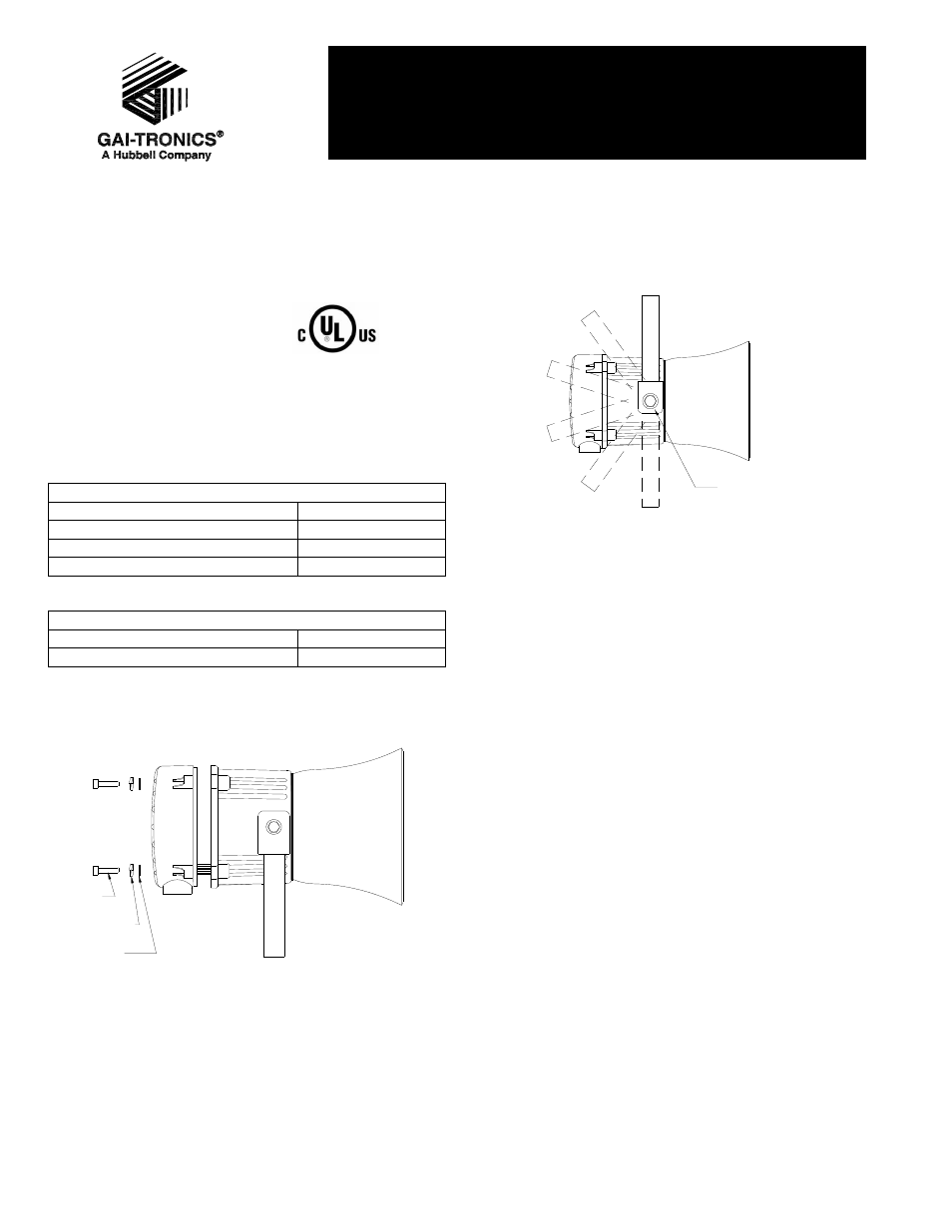
MOUNTING
The 13380 15W loudspeaker must be mounted using the
rotating bracket as shown.
18° Increments
Release nut to rotate
bracket.
WARNING – EXPLOSION HAZARD - SUBSTITUTION OF
COMPONENTS MAY IMPAIR SUITABILITY
FOR CLASS I, II DIVISION 2.
WIRING INSTALLATION
The 13380 15W loudspeaker is provided with 1 M20 x 1.5 cable
entry and one ½” NPT cable entry. The M20 entry is provided
with a stopping plug in place.
Installation using Cable Glands without Field Wiring Leads
The cable connections are made into the terminal blocks on the
electronic PCB assembly. Terminal blocks are suitable for field
wiring (AWG 18-12). Strain relief has to be ensured by
installation with a suitable cable gland. Follow the markings for
the terminals on the PCB and install wiring as shown in the
diagram below.
Cable glands need to be UL certified to ANSI/UL 2225 or C22.2
NO. 174-M1984, and to UL514B / CSA-C22.2 No. 18.3-12,
ratings for hazardous locations must be equal to or better than
the rating of the sounder used.
If a high IP (Ingress Protection) rating is required then a
suitable sealing washer must be fitted under the cable gland.