GAI-Tronics 69253-001 Audio Generator Interface PCBA User Manual
Page 5
Pub. 42004-601L2
69253-001 Audio Generator Interface PCBA
Page 5 of 7
\\s_eng\gtcproddocs\standard ioms - current release\42004 instr. manuals\42004-601l2.doc
2/97
Installation
Warnings: Please observe the following warnings, or damage to the equipment may result.
WARNING
Disconnect power to the card rack prior to installation.
Remove the 69253-001 from its carton. Ensure that power is disconnected to the card rack prior to
installation. Before installing, complete the following jumpers and switch settings on the main PCBA:
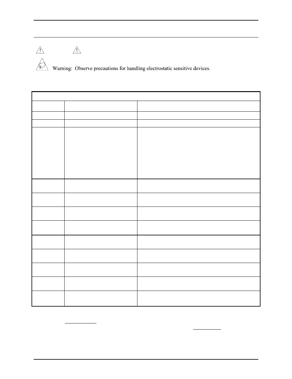
Jumper and Switch Settings
Reference
Designator
Description Valid
Settings
S1
PCBA Address (lower)
1
∅-F (hex)
S2 PCBA
Identification
2
1-E
(hex)
S3
Backup Tone Selection
1: Backup Tone 1 - Steady tone (700 Hz)
2: Backup Tone 2 - Alternating tone (800 Hz and
600 Hz-1 second per tone)
3: Backup Tone 3 - Sweep tone (500 Hz to 1 kHz)
4: Backup Tone 4 - Siren tone (500 Hz to 1 kHz)
5: Backup Tone 5 - Slow siren (500 Hz to 1 kHz)
6: Backup Tone 6 - Steady tone (500 Hz)
7: Backup Tone 7 - Steady tone (1 kHz)
J4
PCBA Address (upper)
1
Pins 1 and 2 shorted: Address 2XX selected*
Pins 2 and 3 shorted: Address 3XX selected
J5
Auxiliary Input Select
Pins 1 and 2 shorted: 33-ohm input selected
Pins 2 and 3 shorted: 600-ohm input selected*
J6
Fail-safe Tone (BP_EVAC+)
Enable/Disable
3
Pins 1 and 2 shorted: Fail-safe tone enabled*
Pins 2 and 3 shorted: Fail-safe tone disabled
J7
Fail-safe Tone (BP_EVAC-)
Enable/Disable
3
Pins 1 and 2 shorted: Fail-safe tone enabled*
Pins 2 and 3 shorted: Fail-safe tone disabled
J8
Supervisory Tone (BP_SPVR+)
Enable/Disable
4
Pins 1 and 2 shorted: Supervisory tone enabled*
Pins 2 and 3 shorted: Supervisory tone disabled
J9
Supervisory Tone (BP_SPVR-)
Enable/Disable
4
Pins 1 and 2 shorted: Supervisory tone enabled*
Pins 2 and 3 shorted: Supervisory tone disabled
J10
Interrupt Select (from MCU)
5
Pins 1 and 2 shorted: AMP IRQ5*
Pins 2 and 3 shorted: AMP IRQ11
J11 Interrupt
Select
(from contact-closure inputs)
5
Pins 1 and 2 shorted: AMP IRQ7*
Pins 2 and 3 shorted: AMP IRQ15
J12
Interrupt Select (from DSP)
5
Pins 1 and 2 shorted: AMP IRQ3*
Pins 2 and 3 shorted: AMP IRQ10
* = Factory default settings
N
OTES
:
1. PCBA address (set by S1 in conjunction with J4) must be set to a unique value (a value not used by
any other PCBA in the card rack).
2. PCBA identification (set by S2) must be set to a value not used by any other AGI in the card rack.
3. J6 and J7 must be set in the same position.
4. J8 and J9 must be set in the same position.
5. J10, J11, and J12 should not be moved from their factory default settings.