GAI-Tronics XCP0010A DC Control Kit User Manual
Page 4
Pub. 43003-012B
Model XCP0010A DC Control Kit
Page: 4 of 4
11/02
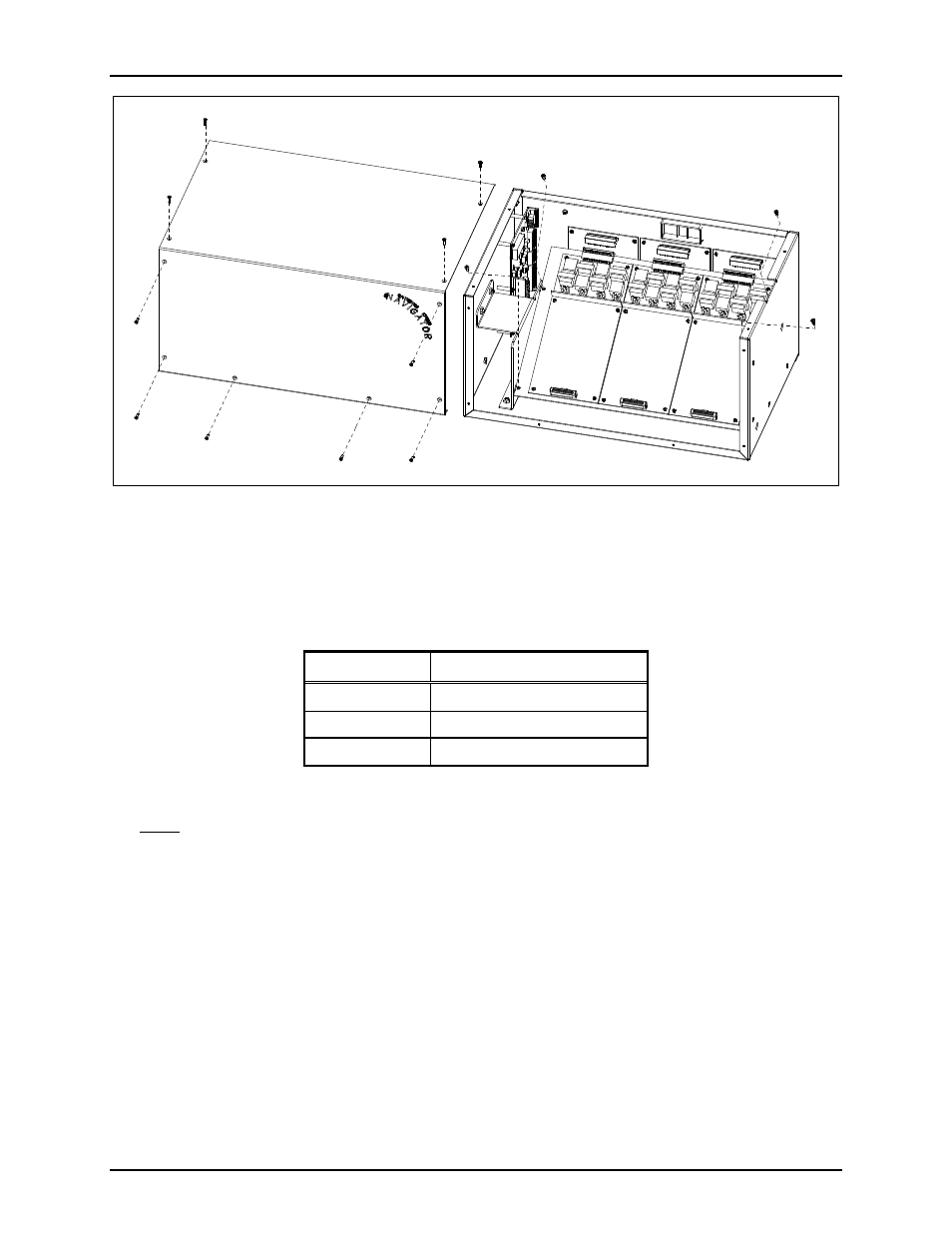
Figure 3.
7. Fasten the CDC PCBA to the inner PCBA mounting plate using the 3 supplied #4-40 screws. See
Figure 2.
8. After the PCBA has been properly mounted, you may reassemble the MCU by reversing the
disassembly procedure. Verify that all CSD-to-main board connections are as follows:
Channel
Main Board Connector
1-4
P1
5-8
P2
9-12
P3
Main Board-to-CSD Slave Board Connectors
Note: The XCP0010A DC Control PCBA has been factory-calibrated to provide the standard control
currents and does not normally require field adjustment.
9. Reconnect power to the ICP9000 Navigator Series MCU.
After the console has been reassembled, it is necessary to program the console by editing the channel
parameters. Refer to your CARD Suite software (XAC1000A) for specific programming instructions.
Also refer to the ICP9000 Navigator Series Operator’s Manual, pub. 43004-025, for user instructions on
dc control operation.