Geist Watchdog 1000 Quick Start User Manual
And clear any, Tempf 74.09, User account
Watchdog 1000-Series quick-setup pack-in sheet (rev.150216A)
1
support available at www.itwatchdogs.com or www.geistglobal.com
+6VDC
ON
REMOTE SENSORS
IP RESET
REBOOT
H
O
R
N
O
F
F
TEMPF
74.09
N
C
N
O
C
N
C
N
O
C
N
C
N
O
C
RELAY1
RELAY2
RELAY3
C
Analog Inputs
1 C 2 C 3 C 4 C 5 C 6
A
C
T
IV
E
ID
L
E
+6VDC
ON
REMOTE SENSORS
IP RESET
C
C
1
2
3
TEMP &
AIRFLOW
SENSORS
L
IG
H
T
S
E
N
S
O
R
H
O
R
N
O
F
F
TEMPF
74.09
A
C
T
IV
E
ID
L
E
+6VDC
ON
REMOTE SENSORS
IP RESET
C
C
1
2
3
A
C
T
IV
E
ID
L
E
R
E
B
O
O
T
REMOTE SENSORS
Watchdog 1000-Series kit will include:
Ÿ Watchdog 1000, Watchdog 1200, Watchdog 1250, Watchdog 1400, or Watchdog 1400P rack-mountable
environmental monitor.
(“Watchdog 1400P” designates a Watchdog 1400 with the Power-over-Ethernet option installed. The
1400 and 1400P are otherwise identical in function and capabilities. Note that the 1400P is the only
model which has a PoE option available; this option is not available on the 1000, 1200, or 1250.)
Ÿ +6Vdc power supply (unless the “no power supply” option was chosen when the unit was ordered)
NOTE: This guide is only meant to assist in identifying your Watchdog 1000-series unit and its included
accessories, if any, and to assist you with initial setup of the unit. It does not describe all of the unit’s features
and capabilities in detail. Please refer to the full user’s manual for complete information about how to use all of
the unit’s capabilities. Also note that for purposes of the following instructions, all members of the Watchdog
1000-series family behave identically, so “Watchdog 1000-series” is used generically to refer to all models.)
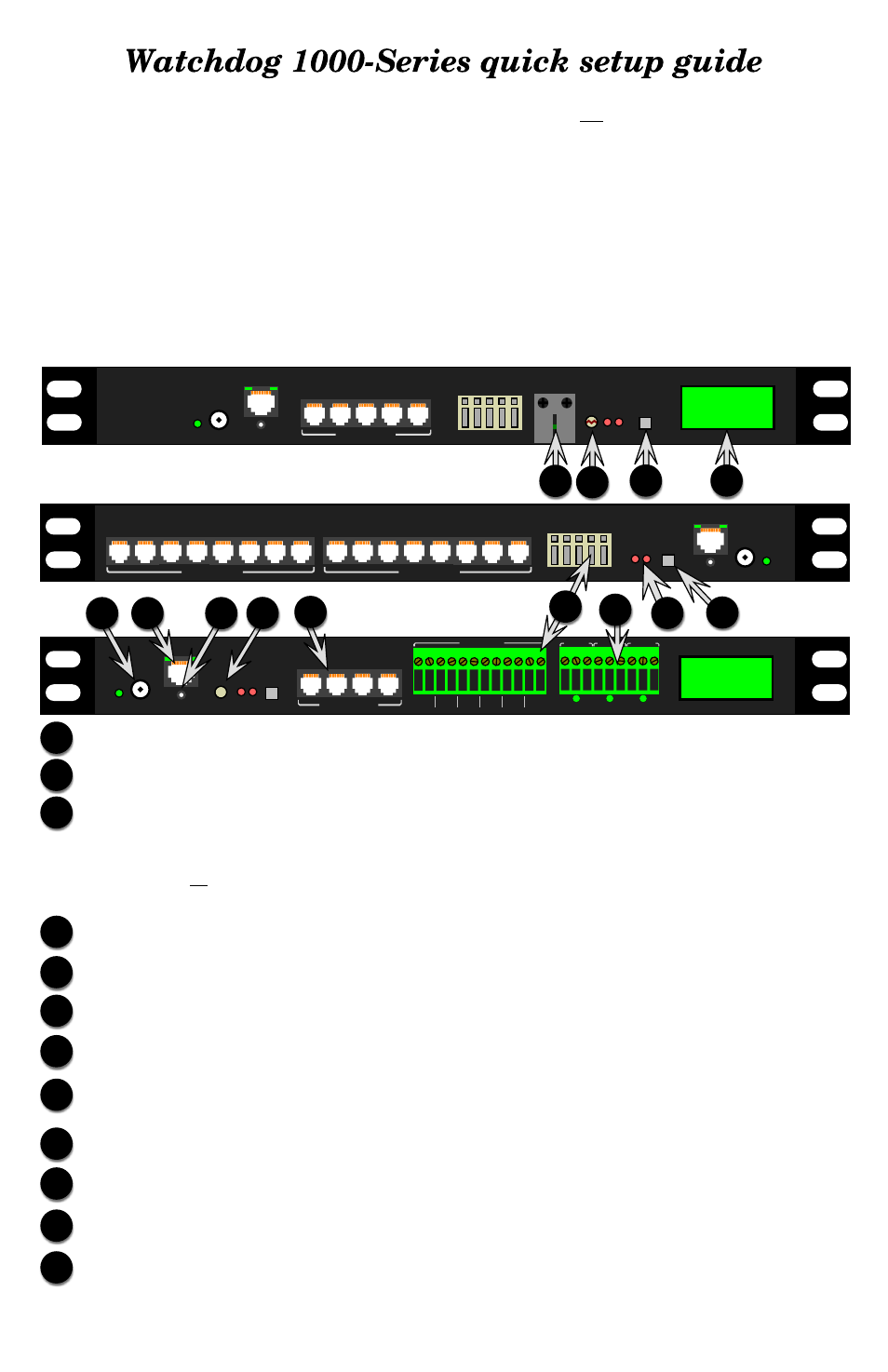
D
Digital Sensor jacks: Up to sixteen Digital Bus-type external sensors may be connected. (may require an
external port-splitter, sold separately)
E
A
DC power jack: +6VDC power supply connects here.
RESET button: To reset the IP address to the factory default of
192.168.123.123
and clear any
User
Account
username/password settings, use a pushpin or paperclip to press and hold this pinhole button for
approximately 20 seconds, until both of the red Active and Idle LEDs light up solidly (no blinking pattern).
To completely erase all settings and reset the unit to factory defaults, disconnect power from the unit, push in the
reset button, reapply power, keep the reset button pushed in for at least 5 seconds, then release.
C
B
Ethernet jack: Right LED indicates “link” when lit; left LED indicates network activity when blinking.
F
Analog Inputs: for dry-contact switches, relay contacts, or analog sensors with 0 ~ +5Vdc output voltages.
G
Relay Outputs: (Watchdog 1400 / 1400P only) Dry-contact relays for controlling external low-voltage
devices. The LEDs under the terminal block shows the relay states: de-energized (red) or energized (green).
Active / Idle LEDs: Indicates that the unit is operating, and communicating with the sensor-bus controller
and external sensors (if any).
H
(sample illustrations only; actual
appearance of unit may vary)
Watchdog 1200 / 1250 (Watchdog 1200 will not have LCD display or “horn off” button)
Watchdog 1000
Watchdog 1400 / 1400P
A
J K
L
M
G
B
C
E
F
D
H
D
REBOOT button: reboots the unit (Watchdog 1000 / 1400 / 1400P only)
Temperature/Humidity/Airflow sensor: Make sure that this is not blocked or covered up when the unit
is mounted. (Watchdog 1200 / 1250 only)
J
Light sensor: (Watchdog 1200 / 1250 only) Measures ambient light level.
K
HORN OFF button: (WatchDog 1250 / 1400 / 1400P only) Silences the internal alarm buzzer even if the
alarm condition which tripped it has not yet been cleared.
L
LCD status display: (WatchDog 1250 / 1400 / 1400P only) Displays unit status information and sensor
measurements.
M