Interfaces on the back panel – Guntermann & Drunck CATpro2-DVI User Manual
Page 7
Installation
G&D CATpro2-DVI-UC · 4
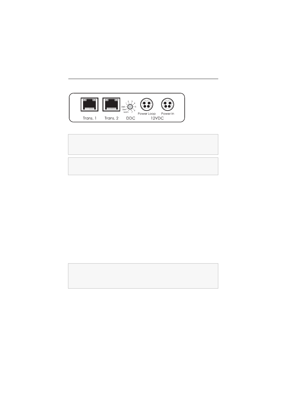
Interfaces on the back panel
Trans. 1: Connect this interface to a CPU port of a CATCenter system. Use a cate-
gory 5 (or better) twisted pair cabling for this purpose.
Trans. 2: Connect this interface to a CPU port of a CATCenter system. Use a cate-
gory 5 (or better) twisted pair cabling for this purpose.
DDC: This rotary switch enables selecting the desired DDC information. The chapter
Selecting DDC information on page 7 provides further information regarding this topic.
Power Loop: Connect a Power Loop cable to this interface if you want to supply ano-
ther target module with the power of the optional AC adapter.
Therefore, this target module has to be supplied with power of the optional AC adap-
ter or of a Power Loop cable.
The chapter Power supply via Power Loop cables on page 10 provides detailed informa-
tion regarding this topic.
Power In: If necessary, connect the optional AC adapter or the Power Loop cable
(that is connected to another target module) to this interface.
Figure 2: Back view of the
CATpro2-DVI-UC target module
The target module provides two Trans. interfaces that enable integrating this target
module into two different CATCenter systems.
Only connect one of the target module’s Trans. interfaces per CATCenter system.
The user is enabled to connect several legs of a twisted pair cabling by using patch
fields and outlets. It is not possible, however, to integrate active components such
as network switches, hubs or repeaters.
When applying the AC adapter or a Power Loop cable, the target module does
not have to be supplied with power through the two USB interfaces.
For redundant power supply, the user is enabled to energise the target module
through the USB Pwr and USB CPU interfaces.