Henry Engineering MULTIPORT User Manual
Multiport, Multi-format audio interface panel
MULTIPORT
DESCRIPTION
The MultiPort panel is a utility interconnect device that facilitates interface between a studio or professional audio system
and external audio devices. MultiPort provides convenient access to system audio inputs and outputs, and allows
connection to digital and analog equipment at both professional and consumer signal levels. Digital I/O can be via either
the AES/EBU or S/PDIF standard. Balanced audio outputs are provided at +4dBu and -50dBu and also unbalanced at
-10 dBv. MultiPort can accept analog inputs at +4dBu (balanced) or -10 dBv (unbalanced). XLR, ¼” TRS, 3.5mm Mini
TRS, and RCA jacks are provided for interface. MultiPort is powered by an external AC power transformer, included.
INSTALLATION
MultiPort can be mounted in a rectangular cutout in studio cabinetry. The cutout should be 11” W x 2 1/2” H. (A rack-mount kit is
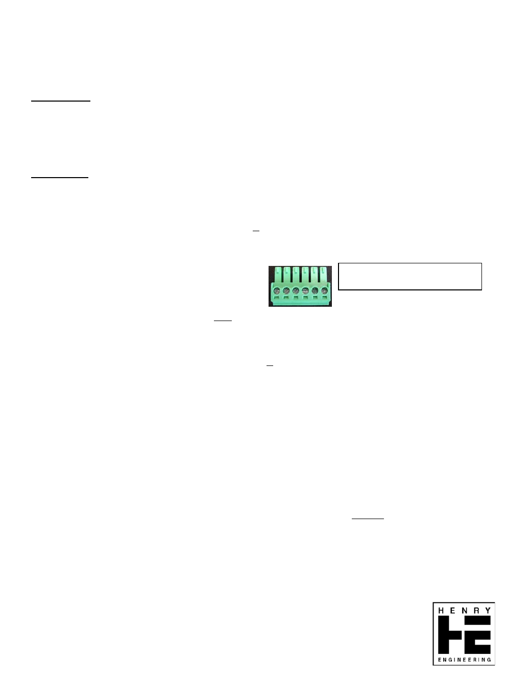
optionally available, for mounting MultiPort in a 2RU rack opening.) Audio and power connections to MultiPort are via three “euroblock”
connectors on the PC board, labeled “To Studio”, “From Studio” and “AES,PWR”. Wire the mating plugs according to the information
below. Note that the pins are numbered left-to-right, with the screws facing up.
TO STUDIO: This connector sends analog audio from MultiPort to the studio, e.g., to a balanced Line input on a console.
All analog wiring to/from MultiPort should be balanced, lo-z, at professional +4 dBu levels.
PIN 1
LEFT +
PIN 2
LEFT –
PIN 3
GROUND
PIN 4
RIGHT +
PIN 5
RIGHT –
PIN 6
GROUND
FROM STUDIO: This connector sends analog audio from the studio (e.g., a DA output) to the MultiPort output connectors.
Pin assignments are identical to those shown above.
AES, PWR: This connector is for the AES digital input and output, and also the power input to MultiPort:
PIN 1
AES + OUTPUT AES digital audio output of MULTIPORT to studio, e.g., the AES input of a digital console
PIN 2
AES – OUTPUT
PIN 3
AES+ INPUT
Studio AES output (e.g., output of digital D.A.) to MULTIPORT digital output connectors
PIN 4
AES – INPUT
PIN 5
POWER INPUT 12V AC input to MULTIPORT (This is also the ground of MULTIPORT internal circuitry.)
PIN 6
POWER INPUT 12V AC input to MULTIPORT
GROUNDING: Grounds of analog I/O connectors can be connected at both ends. Four “jumper pins” (JP1-JP4) allow the studio
equipment grounds to be connected-thru to the XLR Pin1 ground terminals. JP1 (L) and JP2 (R) connect MultiPort input connector
grounds to the grounds of studio input equipment. JP3 (L) and JP4 (R) connect the studio output grounds to the ground pins of
MultiPort output connectors. The AES input and output connections are transformer isolated; no ground connection is required.
(MultiPort metal panel is connected to Pin 6 of the “From Studio” connector.)
OPERATION:
For balanced Line analog inputs/outputs, use the “combo” jacks for inputs (TRS or XLR) and the male XLR output jacks.
For unbalanced “consumer” Line analog inputs/outputs, use the “RCA” phono jacks or 3.5mm TRS jacks. All line-level I/O is stereo.
For balanced Mic-level outputs, use the Mic Output jacks. Note that both the Mic outputs are monaural, and are summed from the left
and right studio outputs. The Mic Ground switch can be used to disconnect Pin 1 of the Mic output XLRs from the studio ground.
To feed a digital audio signal into MultiPort, use either the AES input (XLR) or the S/PDIF input (RCA). Do not use both input jacks at
the same time. MultiPort’s digital outputs are available on either the AES output (XLR) or S/PDIF output (RCA). The Digital Output
Select switch selects which output is active. Do not use both outputs at the same time.
The two digital Utility connectors can be used for pass-thru connections of USB and RJ45 cables. Note that the USB connectors are
reversible, and can be installed with either type of USB connector facing outwards. Either of these connectors can be field replaced
with Neutrik USB, RJ45 or IEEE-1394 (“Firewire”) connectors.
Specifications subject to change without
notice.
Rev.
01/2010
1 2 3 4 5 6
Pins are numbered left-to-right,
with screws facing UP.
HENRY ENGINEERING
503 Key Vista Drive
Sierra Madre, CA 91024
Tel: 626-355-3656
Web: www.henryeng.com
TM
Multi-Format Audio Interface Panel