Herrtronic, Mdd supplement – Herrmidifier Herrtronic MDD User Manual
Page 7
Herrtronic
®
MDD Supplement
I n s t a l l a t i o n , O p e r a t i o n , & M a i n t e n a n c e M a n u a l
7
www.herrmidifier-hvac.com
V. STEAM DISTRIBUTION
Refer to Herrtronic MD IOM for detailed instructions. See Figure 3 on page 9 – Unit Dimensional Data for steam outlet locations.
VI. SUPPLY POWER
Power Block is supplied in the lower right hand side of the electrical compartment for field connection of the main power supply legs
(always three phase) and a ground wire. Engineering Data: Steam Output / Electrical Characteristics
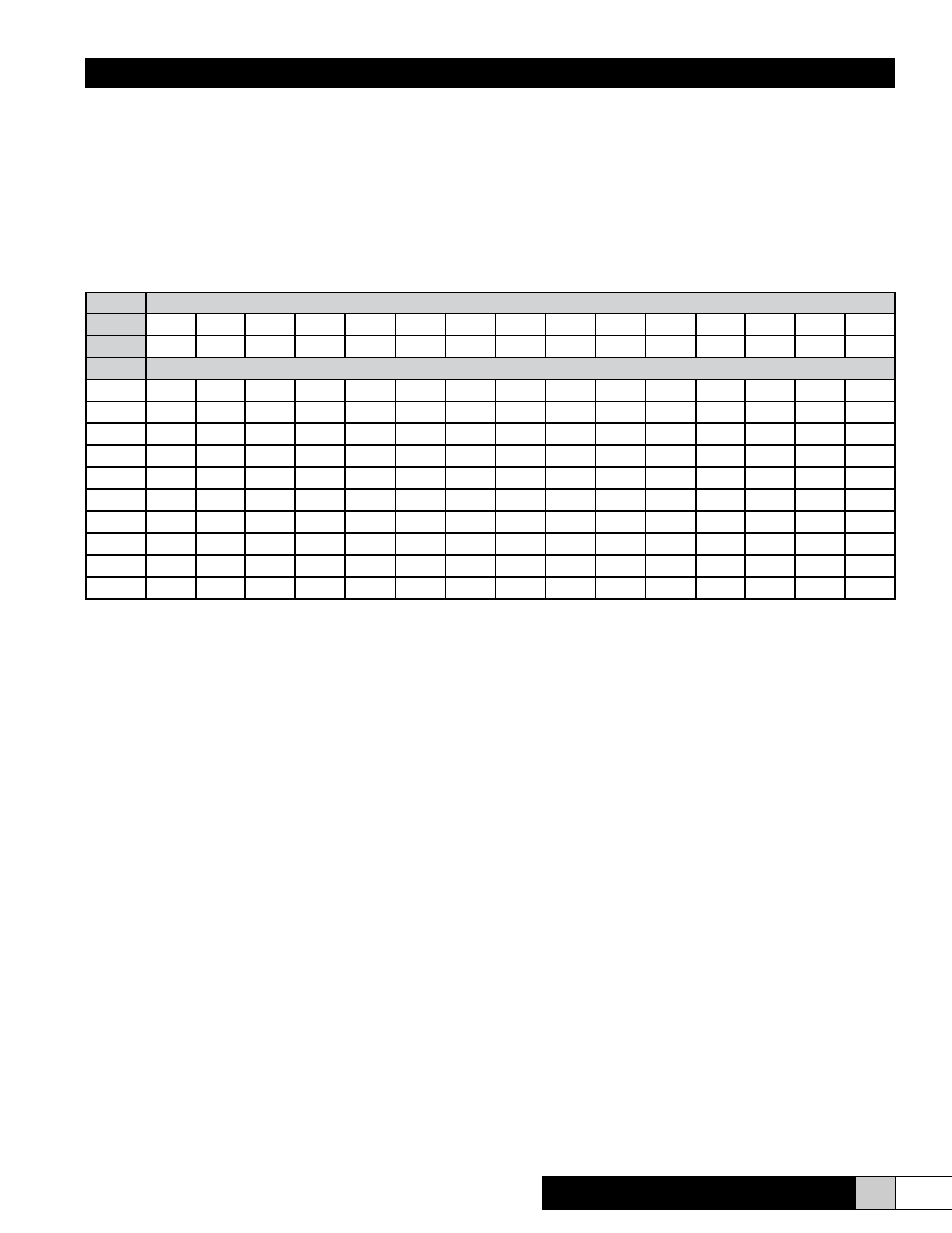
Figure 6 - Steam Output/Electrical Characteristics:
KW = .333 X Lbs/Hr
Amps(3Ph) = KW X 1000 / (Voltage X 1.732)
Min. Circuit Ampacity = 1.25 X Rated Electrode Current (Note: with RDU add .5 Amps @ 208/240 Volts or add .25 Amps @ 480 Volts)
Minimum Circuit Ampacity determines wire size (AWG)
Refer to Herrtronic MD Installation, Operation, & Service manual for additional information.
VII. MDD CONTROL CIRCUIT CONNECTIONS
Dependent Control
This is the typical control circuit application for the MDD units. In this configuration, the MASTER and SLAVE equally share the total
output That is, for a 140 lbs/hr. MDD, the MASTER will produce 70 lbs/hr. and the SLAVE will also produce 70 lbs/hr. If the MDD
has the capability to modulate its output (MDDI or MDDP), the output of the MASTER and the SLAVE will remain equal throughout
the proportioning range.
The Dependent MDD requires one set of controls; a control input, a recommended limit input and air proving switch. See pages 10
and 11 of the MD IOM for proper placement of the control wires to the appropriate pole(s) on the master unit terminal strip.
Independent Control
In this configuration, the MASTER and the SLAVE may be rated for different output capacities. The data plate will reflect the com-
bined output and current draw. If the output capacities of the MASTER and SLAVE are different, the MASTER will always be the
larger of the two unless specified otherwise when ordering.
The Independent MDD requires two sets of controls; two control inputs along with the recommended individual limit inputs and air
proving switches. The MASTER and SLAVE input connections will be made on their respective terminal strips (Figure 7). Refer to
the Control Circuit Connections section of the MD IOM (pages 10 and 11) for proper terminal connections for your particular type of
controls. The units will operate independently of one another, with the circuit boards responding to their individual inputs.
Steam Output
Lb/hr
110
120
130
140
150
160
170
180
190
200
210
220
230
240
250
Kg/hr
50.0
54.4
59.1
63.6
68.2
72.6
77.3
81.7
86.4
90.9
95.5
100
104.5
109.1
113.6
Voltage
Electrode Current (amps)
208
101.7A 110.9A 120.2A 129.4A 138.6A 147.9A 157.1A 166.4A 175.6A 184.9A
220
96.1A 104.9A 113.6A 122.3A 131.1A 139.8A 148.6A 157.3A 166.0A 174.8A
230
91.9A 100.3A 108.7A 117.0A 125.4A 133.7A 142.1A 150.5A 158.8A 167.2A
240
88.1A
96.1A 104.1A 112.2A 120.2A 128.2A 136.2A 144.2A 152.2A 160.2A
380
55.7A
60.7A
65.8A
70.8A
75.9A
81.0A
86.0A
91.1A
96.1A 101.2A 106.2A 111.3A 116.4A 121.4A 126.5A
440
48.1A
52.4A
56.8A
61.2A
65.5A
69.9A
74.3A
78.7A
83.0A
87.4A
91.8A
96.1A 100.5A 104.9A 109.2A
460
46.0A
50.2A
54.3A
58.5A
62.7A
66.9A
71.1A
75.2A
79.4A
83.6A
87.8A
91.9A
96.1A 100.3A 104.5A
480
44.1A
48.1A
52.1A
56.1A
60.1A
64.1A
68.1A
72.1A
76.1A
80.1A
84.1A
88.1A
92.1A
96.1A 100.1A
575
36.8A
40.1A
43.5A
46.8A
50.2A
53.5A
56.8A
60.2A
63.5A
66.9A
70.2A
73.6A
76.9A
80.2A
83.6A
600
35.2A
38.5A
41.7A
44.9A
48.1A
51.3A
54.5A
57.7A
60.9A
64.1A
67.3A
70.5A
73.7A
76.9A
80.1A