J7: cf socket, J9: spi flash connector (factory use only), J12: audio connector – IBASE IB885 User Manual
Page 23: J13: usb0/usb1 connector
INSTALLATIONS
Power LED: Pins 3 and 4
Pin #
Signal Name
3 Vcc
4 Ground
Hard Disk Drive LED Connector: Pins 5 and 6
This connector connects to the hard drive activity LED on control panel.
This LED will flash when the HDD is being accessed.
Pin #
Signal Name
6 HDD
Active
5 Vcc
Reset Switch: Pins 7 and 8
The reset switch allows the user to reset the system without turning the
main power switch off and then on again.
J7: CF Socket
J9: SPI Flash Connector (factory use only)
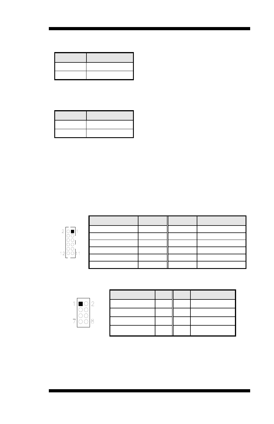
J12: Audio Connector (DF11 Connector)
Signal Name
Pin #
Pin #
Signal Name
LINEOUT R
2
1
LINEOUT L
Ground
4
3
JD FRONT
LINEIN R
6
5
LINEIN
Ground
8
7
JD LINEIN
MIC-In
10
9
MIC L
Ground
12
11
JD MIC1
J13: USB0/USB1 Connector
Signal Name
Pin Pin
Signal Name
Vcc 1
2
Ground
D0- 3
4 D1+
D0+ 5
6 D1-
Ground 7
8 Vcc
Note: This USB connector is compatible with USB 2.0 devices only.
IB885 User’s Manual
19