IBEA Attrezzi User Manual
Page 36
GB
ENGLISH
36
BRUSHCUTTER
ASSEMBLY SAFETY GUARD Fig. 30
Mount the total protection (A + H) on the transmission
pipe (B) and secure using the jumper (C), screws (D),
piatrina (G) and nuts (F).
IMPORTANT: Make sure the jumper (C) is fixed to
the conical torque (L) through the screw and
washer (E). CAUTION: Use protection (A + H) with the
head of a nylon wire. Use only the protection (A) with the
lame.Per reasons of safety, the saw blades can not be
used with no protection provided.
BLADE ASSEMBLY Fig. 31-32
- Loosen the nut (1) clockwise; remove cup (2) (only if is the
skid unit version) and lower flange (3).
- Fit the blade (4) as showed in the picture making sure that
the upper flange (5) is well fitted.
- Fit the blade making sure that the rotation direction is correct
(the inscription on the blade should be facing up).
- Fit the lower flange (3), the cup (2) (only if is the skid unit
version) tighten the nut (1) anti-clockwise at 30 Nm (3.0 kgm).
- While tightening the nuts (1), the blade can be held fast by
inserting the allen key Ø 4 mm into the cap, the upper flange
and gear case holes. To do this, rotate the cutiing tool until
the two holes coincide.
NYLON HEAD ASSEMBLY Fig. 33-34
Mount the head of a nylon wire following the Illustrated:
upper flange (1) and turn clockwise to the head of nylon
threads.
Tighten by hand clockwise head as shown in Fig.10 after
entering the Allen key (4 mm) in the conical bore of the
pair.
For your safety, use only original cutting tools.
TILLER
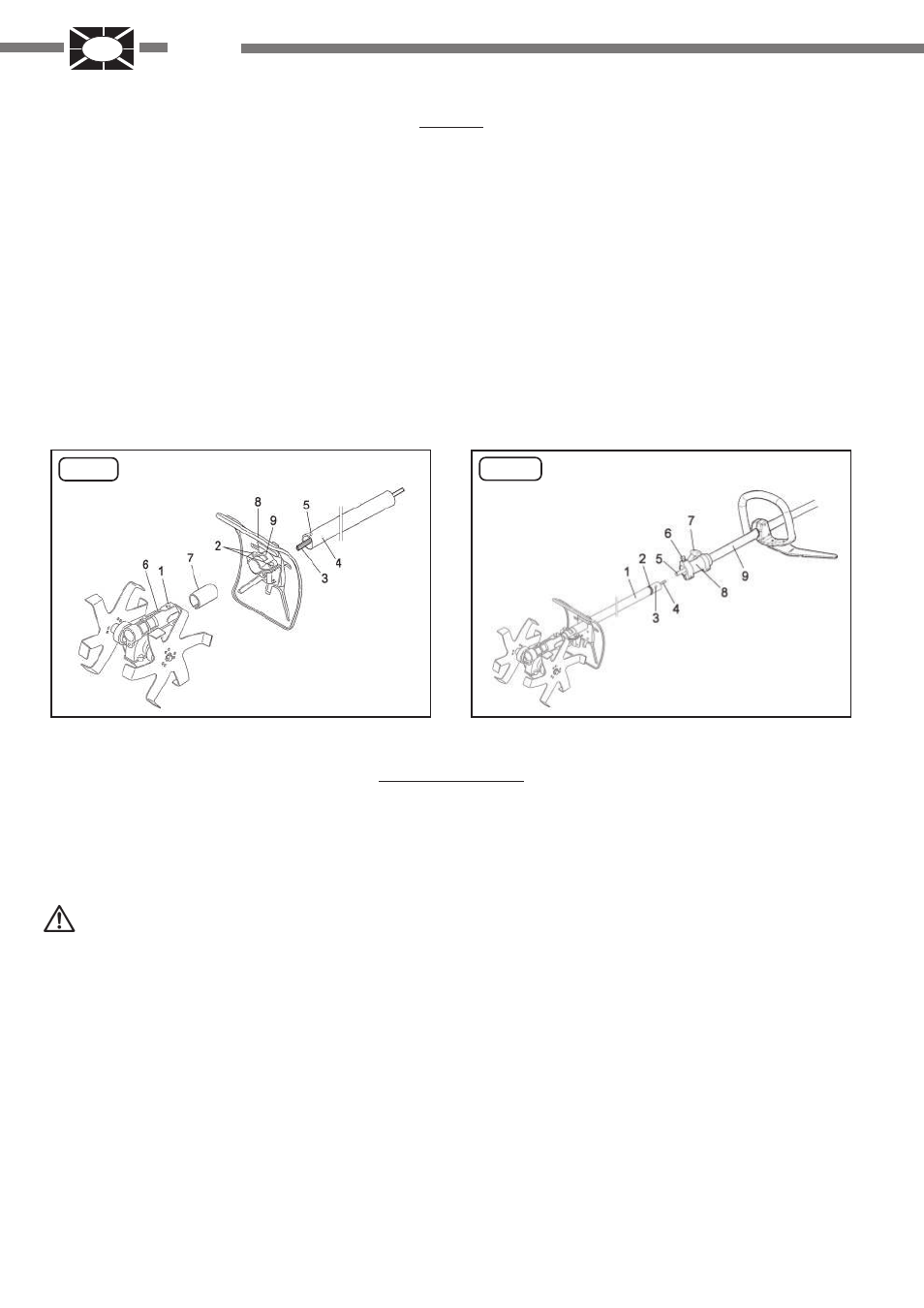
INSTALLING THE ACCESSORY TUBE - TILLER
ATTACHMENT Fig. A
- Unscrew the 2 screws (2) and remove the plate (9)
- Loosen screw 1
- Insert the accessory tube, from the part upon which the tip
of the shaft is grooved (3), into the hole of the protective guard
(8) and then into the tiller unit (6)
- Tighten screw 1, making sure that it is aligned with hole 5 on
the transmission tube
- Mount the plate (9) and tighten the 2 screws (2)
- Only use the adaptor (7) between the accessory tube and the
plate (9), if you have a Ø 24 accessory tube.
INSTALLING THE ACCESSORY TUBE - MOTOR TUBE
Fig. B
- Turn the lever (7) counter clockwise to unscrew it
- Lift the pin (6)
- Insert the tube (3) into the sleeve (8) down to its
reference point (2)
- Make sure that the pin (6) is aligned with the hole (3)
- Make sure that the attachment's transmission shaft (4)
is inserted into the motor's transmission shaft (5)
- Screw in the lever (7) by turning it clockwise
MOTOR
For the assembly and adjustment procedures relative to the
machine, see the specific user and maintenance manual for
the machine typology in your possession.
FIG . A
FIG . B
If the installation has been completed successfully, the
tiller's two disks will turn when the transmission shaft is
turned manually.