4 diagnostic and adjustments, Installation – IHSE USA 234 Series VTO2/VRO2 KVM-Extender User Manual
Page 21
INSTALLATION
21
3.4 Diagnostic and Adjustments
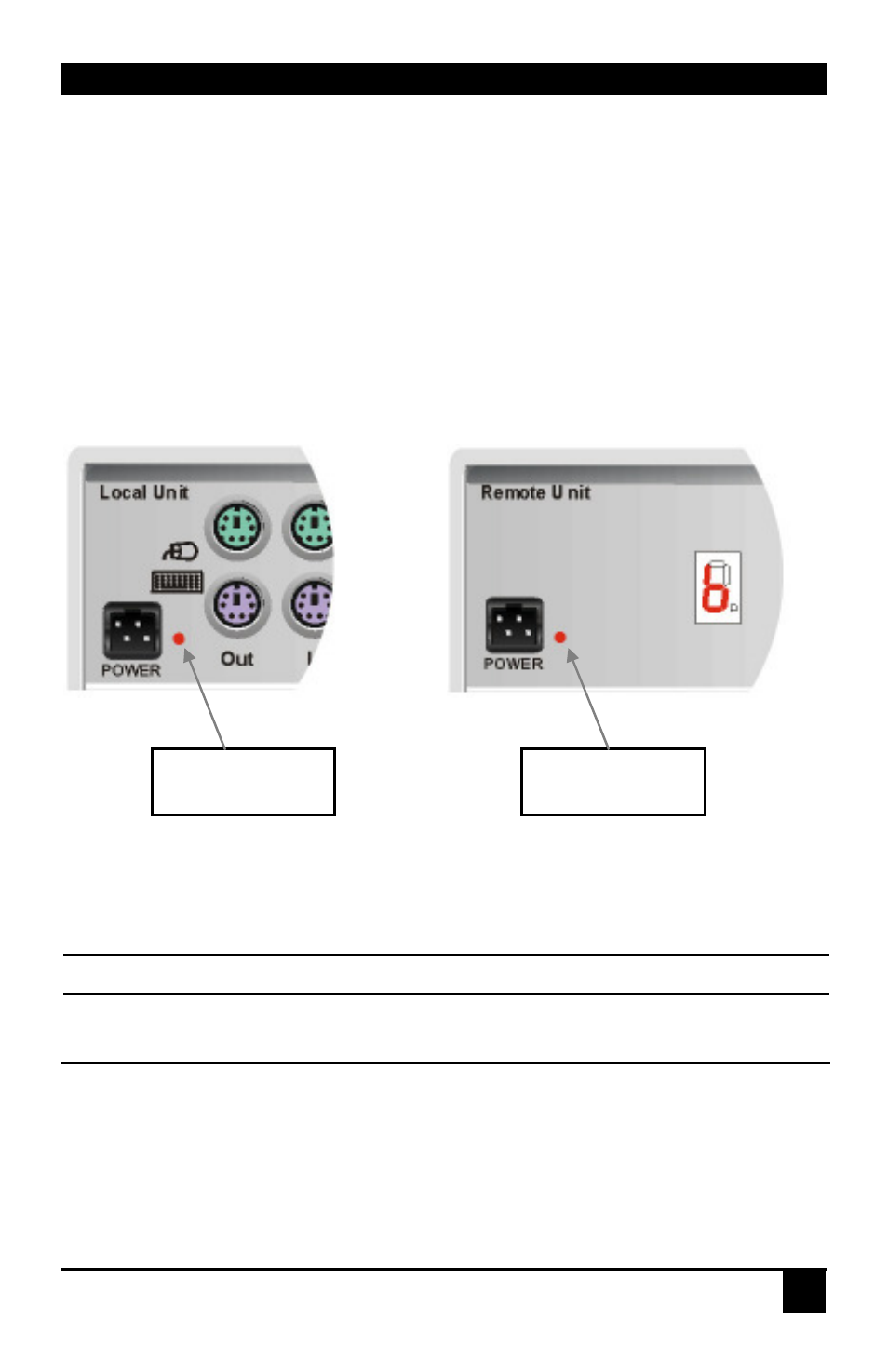
Each VTO2/VRO2 V6.00 KVM-Extender is fitted with an indicator LED Device Ready and a
7-Segment display for enhanced troubleshooting: The Device Ready LEDs are next to the
power sockets. The 7-Segment display is next to the power socket of the remote unit.
On each VTO2/VRO2 V6.00 KVM-Extender you can adjust Brightness and Contrast
manually. In addition, each colour can be adjusted manually (only with automatic gain
control – AGC = OFF). The potentiometers to adjust Brightness and Contrast are to the right
of the fibre connectors on the Remote unit. The 7- Segment display is next to the Power
socket of the Remote unit.
The location of the LEDs is shown below:
Diagnostic LEDs on VTO2/VRO2 Extender
LED
Appearance
Diagnostics
Device Ready
(Red LED)
Off
On
Device not ready
Device ready
Diagnostic LED
Device Ready
Diagnostic LED
Device Ready