ILS Presentation Systems User Manual
Page 2
2
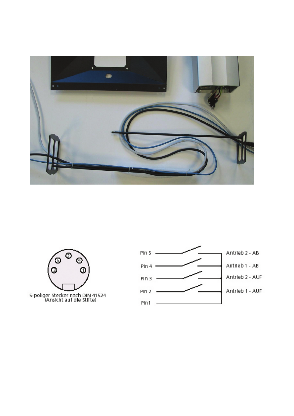
To accommodate for the wide range of height adjustment, the cables are managed in an S-curve that is almost
straight when the pillar is at top height, allowing for at least 30 cm of cable margin on the top to plug into the
ILS22 I/O bay. See figure 2. The picture is for clarity, now first put all needed cables from the bottom end through
the pillar so that they appear at the top
Figure 2.
Now tie the cables together on the top rod of the cable managers, include a tie wrap through the eye, and insert
this into the top of the pillar (while still in its low position). You may loosely put screws in to hold this in place.
Once completed, temporarily apply power to the pillar. Short on the DIN socket (see figure 3) the pins 1 and 2 to
make the pillar come out all the way, this will tell you how long the cables must be inside.
Then shorten 1 and 4, to make the pillar go to its lowest point.
Now that you know the length of the cables, tie the cables to the bottom cable manager and insert this inside the
pillar. Now you can mount the pillar on the foot. And fasten the bolts tightly.