Infloor Heavy-Duty Cable User Manual
Slab construction, Hardwood flooring, Frame construction
* Masonry Mass refers to any dry pack, sel eveling
product, light weight bedding mortar, and all mortar
based aggregates.
** To secure the cable use either hot melt glue,
cable clips, or 3/8’’ crown staples. Or put down wire
mesh and secure with wire ties or duct tape.
*** Finished
g refers to tile, marble, or radiant
compliant carpet, hardwood, and laminates.
This SPACING FORMULA must be used to calculate spacing between cables.
AREA (sq. ft.) x 12 ÷ LENGTH OF CABLE = On Center SPACING
(Cable length noted on UL tag.)
Example:
Area In Squarefeet
=
85 sq.Ft.
85x12= 1020 = 5.28” OnCenter
Cable length
= 193 Ft.
193
TXLP/2R Series Electric Floor Heating Cable Instructions
Installation Of The Heating Cable
IMPORTANT NOTE: THESE CABLES ARE NOT TO BE INSTALLED IN WALLS OR CEILINGS FOR ANY REASON
AND ALL ELECTRICAL CONNECTIONS MUST BE PERFORMED BY A QUALIFIED, LICENSED ELECTRICIAN.
NEVER:
Cross the blue heating cable over itself.
Cut the blue heating cable for any reason.
Run blue heating cable directly into the junction box.
Subject any part of the cable to harmful surfaces.
GROUND RATED INSULATION
***FINISHED FLOORING
REINFORCED CONCRETE
**HEATING CABLE, IN NEW SLAB
OR ON TOP OF EXISTING SLAB.
MAXIMUM 2’’ FROM SURFACE.
SLAB CONSTRUCTION
CRUSHED ROCK OR STONE
Typical Cable Installations
HARDWOOD FLOORING
SUB-FLOOR
(SLAB OR PLYWOOD)
HEATING CABLE
NAILS
*MIN. 5/8" MASONRY MASS
(ASSURE NO AIR GAPS)
SLEEPERS
HARDWOOD FLOORS, ONE
COVERING, MINIMAL THICKNESS
INSULATION
INSULATION
(OPTIONAL, RECOMMENDED)
***FINISHED FLOORING
SUB-FLOOR PLANKING
**HEATING CABLE
(*
) MASONRY MASS
MIN. 5/8”
FRAME CONSTRUCTION
(OPTIONAL)
(OPTIONAL)
ALWAYS:
Follow local and national electrical codes.
Test the cable for the proper readings before, during and
after the installation.
Make certain both splice and bulb are buried in the pour.
Fill out the warranty card and return it to Orbit.
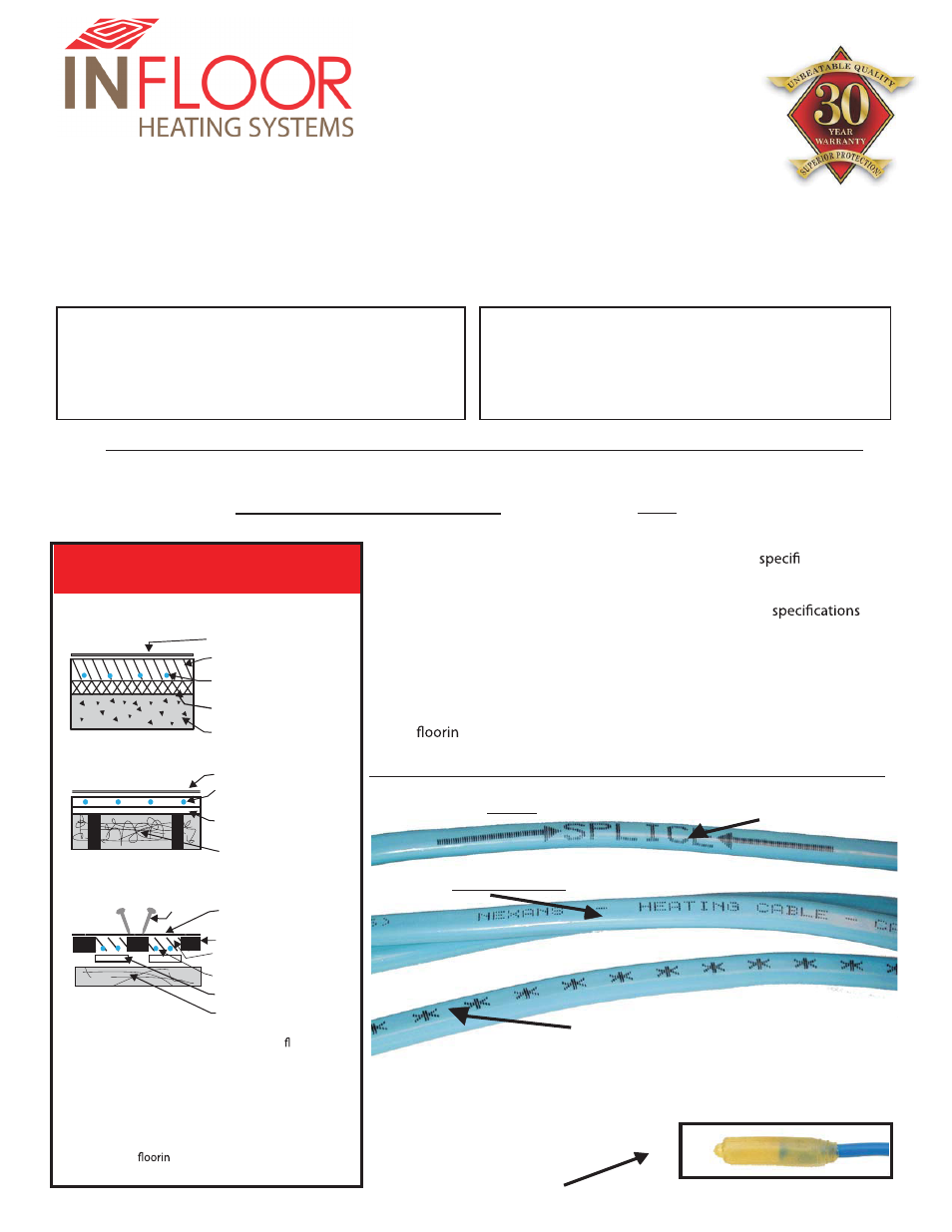
*Identifying the Nexans TXLP Manufactured Heating Cable*
Cold lead “
”, marked about 7’ from the start of cable.
Splice
Actual “
” located between the splice and bulb.
Heating Cable
The TXLP/2R Series Cable box sets are pre-engineered units available
for both 120 and 230 volt applications. Each cable has a
c length,
wattage, and ohms resistance reading. It is important that you supply
the TXLP/2R Heating Cable with the voltage it is designed and tagged
for. The heating cables are factory designed under precise
and cannot be altered for any reason and are not interchangeable with
other cable. IT IS VERY IMPORTANT TO NEVER CUT THE HEATING
CABLE as this will damage the cable and void the warranty. Both splices
MUST be buried in the masonry. These are the points where the cable is
attached to the cold lead, and on the opposite end where the heating
cable ends with the bulb. Note the thickness of the bulb when pouring
your
g material to embed the cable. Only the cold leads can be out
of the masonry or concrete and run into the conduit.
‘‘Bulb’’ located on the end of
the heating cable.
Buena Vista, CO 81211
(800) 608-0562
(719) 395-3555
P.O. Box 4945
Factory
‘’Cold Lead” identified by asterisks,
presented on the full length of cold
lead.
Please Note: asterisks may not be
located at the beginning of the cable.