Phase 1: design the system, Step 1.1 – Infloor Standard Electric Cable User Manual
Page 3
Infloor Installation Manual
3
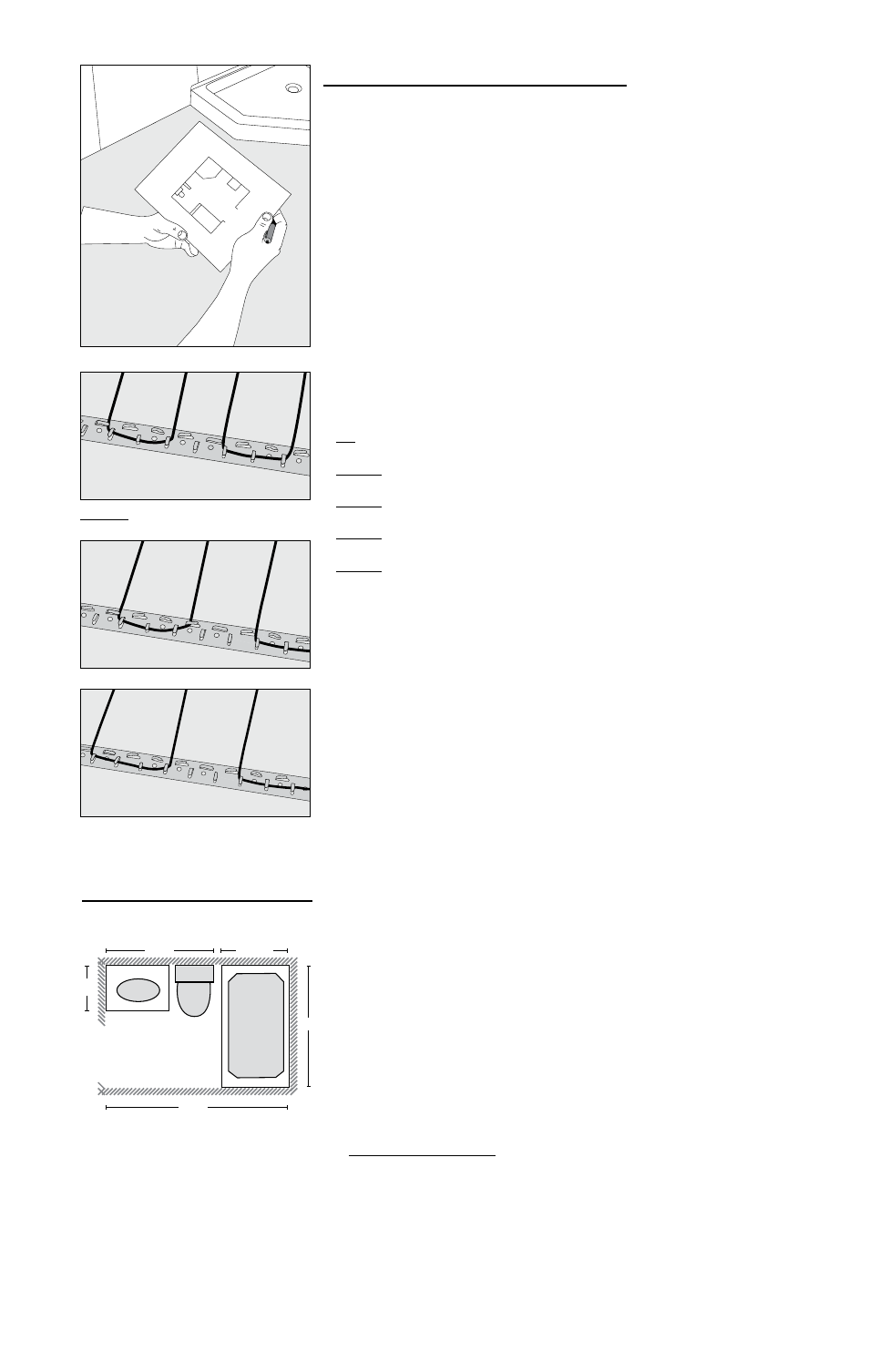
2” spacing
2-1/2” spacing
3” spacing
NEVER exceed 3” spacing.
Small bath design
NEVER use less than 2” spacing.
STEP 1.1
Phase 1: Design the System
Infloor Electric Cable should be installed in all interior floor areas that are to be
warmed. It cannot be used for exterior applications, snow melting, or in ceil-
ings. In some applications, it can be used to heat the room as well, but in gen-
eral it is not designed for this purpose (heat-loss calculations must be made to
determine if enough heat will be provided to match the heat loss of the room) .
STEP 1.1 Make a sketch of the room . Measure the total square footage of
floor area to be warmed (measurements should be made all the way to the
edge of walls, cabinets, tub, etc ., for now) . Keep in mind the following:
• Heat will not radiate beyond about 1-1/2” on either side of the cable,
therefore consistent coverage is important .
• The cables can be installed in permanent bench seats with tile or stone
coverings .
• Type (-W) cables only (see UL Label on product) may be installed into
shower floors and bench seats. However, do not install them into the walls.
Consider installing a dedicated cable in the shower area separate from the
rest of the bath floor. In case there is ever a problem with the shower instal-
lation, this cable could be disconnected without loss of heat to the rest of
the floor. Acceptance of this shower application must be verified by
the local inspector or authority having jurisdiction. See Step 5.20 and
Appendix 5 for details and precautions.
• Do install cable within about 1-1/2” to 2” from a counter or vanity in the
kick-space to ensure warmth in this area .
• Do not install the cables underneath cabinets or fixtures or inside a
wall . Excessive heat will build up and cause damage .
• Do not run the cables into small closets or other confined areas where
excessive heat will build up .
• Do not install the cables closer than 6” from toilet rings to avoid
possible melting of wax rings .
• Do not cross expansion joints . Install the heating wires 4” to 6” away from
the perimeter walls of the room . This will help avoid locating heating wire
underneath finish trim .
STEP 1.2 Select the cable spacing . Below are typical spacings for various
types of rooms . This spacing can vary depending on the insulation of the floor
and room, and the desired effect . Never space cables closer than 2” apart; this
will cause a very hot area and may cause damage .
Typical uses:
• 2” spacing: Sunroom floors, basement slabs, and baths with exterior
walls . (NOTE: Insulation is always recommended due to high heat
losses in these areas . Performance is never guaranteed due to
construction and climate differences in these applications .)
• 2-1/2” spacing: Bathrooms, kitchens, living areas, and basements .
• 3” spacing: Hallways, entryways, and large areas with low heat loss .
STEP 1.3 Multiply the square footage measured in Step 1 .1 by 0 .90 to allow
for 3” spacing around the edges of the floor area . Use this resulting square
footage to select the appropriate cable from the tables on page 4 .
Remember:
• Do not place over 15 amps at 120 VAC (1800 watts) or 15 amps
(3600 watts) at 240 VAC through a control.
• Select either 120 VAC or 240 VAC depending on the power available.
DO NOT mix voltages on the same system if more than one cable is
to be installed to cover an area .
• Load no more than 12 amps (1440 watts) on a 15-amp circuit breaker,
or 16 amps (1920 watts) on a 20-amp circuit breaker .
• If you have an area that requires more than 15 amps of cables to be
controlled by one thermostat, use Infloor Relay(s) to take the
additional amp load .
• See the Wiring Diagrams in Appendix 2 for help.
If the exact size of cable calculated is not found in the spool selection
tables on page 4, it may be necessary to adjust the warming area(s) or select
the next smaller spool size . Remember, the cable must never be cut shorter
to fit, and must be embedded completely in mortar in the floor. Be careful
not to select a spool that is too large.
STEP 1.4 Strapping is included to secure the cable to the floor . Additional
strapping can be ordered . One box contains 25 ft . of strap, enough to prepare
about 50 sq . ft . of floor at 4-ft . spacing . Strap is usually spaced every 3 to 4 ft .
Use of methods to secure the cable other than those described in this Manual
voids the Warranty and are not allowed unless authorized by the manufacturer
in writing . Do not use nails, staples, or similar.
Gross Room Area: 8 x 5 = 40 sf
Built-in Areas
Sink and Toilet: 2 x 5 = 10 sf
Bath Tub: 2.5x 5 = 12.5 sf
Total Heated Area: 40 - (10 + 12.5) = 17.5 sf
Wire Coverage: 17.5 x 0.90 = 15.75 sf
Chosen Size: 15 sf.
Sink
Toilet
Bath Tub
8 ft
5 ft
2-1/2 ft
5 ft
2 ft