Infloor Thermostat 29019 User Manual
Instruction manual
Installation
1. Look for a location, which has a constant temperature in the house
and it is not near the door entry or air condition outlet (see example
on Figure 1).
Digital Thermostat P/N: 29019
Infloor Sales & Service SW
503 Gregg Drive
Buena Vista, Co 81211
(800) 608-0562
www.infloor.com
SPECIFICA TIONS:
Display Format: Liquid Crystal Display(LCD)
Power Input: AAA battery x 2
Contact Rating: 7A Resistive (3A inductive)
Sampling Rate: 1 Minute
Accuracy: 1°F
Temperature Control Range: 40-95°F
User selectable 3 mins. anti-short cycle delay
Differential selection: 0.5, 1.0, 1.5, 2.0°F
EEPROM (memory) for setting backup
±
1
3
5
7A
NC
C
NO
WIRING DIAGRAMS:
INSTRUCTION MANUAL
Figure 2
Figure 1
Figure 3
Figure 4
Figure 5
8. Snap back the terminal cover and
put the front cover back to the
base. Make sure the hooks on the
base are locked with front cover.
9. You can turn on the main power
switch for operation.
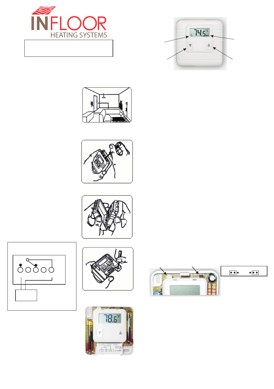
Up Arrow:
Increase Temperature
Setting and Operation:
1. When the thermostat is powered up, setpoint (default is 70
will be flashing for three seconds. Then the current room
temperature is displayed. Press either Up Arrow or Down Arrow
once to display current set temperature. Press once more to
enter setting mode and LCD display will indicate a flashing
temperature with “Temperature Set” and “Heat On” symbols as
shown above.
2. Press either Up Arrow or Down Arrow to set a desired
temperature. Every press on Up Arrow will increase 1°F and
every press on Down Arrow will decrease 1°F. Press and hold to
change the setting continuously.
3. When you have completed setting your desired temperature,
please wait for 5 seconds until the LCD display stops flashing.
Then the thermostat starts to operate to maintain your set
temperature. The LCD display on the front panel indicates the
current room temperature. When the thermostat is calling for
heat, “Heat ON” symbol appears on the LCD display until the
temperature reaches your set temperature.
To view the setpoint:
Press either Up Arrow or Down Arrow once.
Differential Selection:
The differential(Hysteresis) sets the temperature variation the
system allows below the temperature setpoint before switching
on the heating control. To change the differential setting, press
both Up Arrow and Down Arrow buttons at the same time for 5
seconds (The LCD display will show “dif SET”) until the current
value is displayed. Use Up or Down Arrow to select a new
differential value (0.5, 1, 1.5 or 2.0 ). After 5 seconds the
display will return to normal operation. Default is 1 .
Anti-Short Cycle Delay:
°F
)
°
F
°F
Anti-Short Cycle Delay can be set to ensure the output relay remains off
for 3 minutes after relay is de-energized. This feature can be used to
protect the heating equipment such as pump. Use the jumper to turn
on/off the delay function. Default is OFF. Press the Reset Button once
after changing the setting.
Heat On
Symbol
Down Arrow:
Decrease Temperature
Temperature Set
Symbol
Heating
Control
2. Warning!! Turn off your main
power switch before installing the
thermostat.
3. Open the front cover by using a
screwdriver to press a hook on top
of the front cover(see Figure 2).
Pull the front cover out with your
hand holding on both sides of the
cover(See Figure 3).
4. Remove the snap-on terminal
cover(printed with wiring diagram)
by pulling it out with your index
finger with a little bit of force.
5. Use the screws provided, mount the
base on the wall with screwdriver
(see Figure 4). The wires should go
through the lower part of the base
right below the terminal block into a
hole on the wall.
6. Follow the wiring diagram on
Figure 5. Insert the wires into the
terminal block and use a
screwdriver to tighten the screw on
top of the terminal block Before
wiring, you MUST check your
system-wiring diagram. If your
system is other than this type,
please consult with your local
dealer or a professional electrician.
Delay OFF
Delay ON
Jumper location
Figure 6
7. Install the two AAA batteries as
shown on Figure 6.
Reset Button