0 mounting, 1 suggested panel cut-out – Interlink Electronics MicroModule USB User Manual
Page 7
www.interlinkelectronics.com
5
USB MicroModule
Integration Guide
5.0 Mounting
MicroModule requires less than 10 mm of mounting depth (much less than trackballs or
joysticks), allowing it to be easily integrated into tight, cramped spaces. MicroModule’s slim
mounting profile and small front-panel mounting area frees valuable space for other system
components. MicroModule is unaffected by mounting orientation: it can be mounted
horizontally, as in a desktop keyboard; vertically, as on a machine control panel; or any angle in
between. This gives system designers maximum flexibility with product design and ergonomics.
MicroModule is designed to be blind-mounted into a variety of panel types. Additionally, custom
bezels can be fabricated or molded to allow integration into devices such as machine control
panels or notebook computers. A detailed 3D CAD model of Interlink’s suggested mounting
method and geometry can be found on our website at
www.interlinkelectronics.com/Support
.
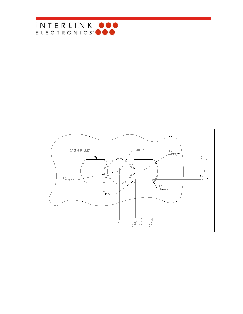
5.1
Suggested Panel Cut-out
When mounting MicroModule, the suggested clearance for the cut-out around the actuator
(Finger Disk or Mini Joystick) is 0.5 millimeters and 1.0 millimeter for the click buttons. See
Figure 4 for details on the suggested cut-out.
Figure 4: Suggested panel cut-out dimensions. All dimensions are in mm and Reference.