Interlink Electronics Ring Sensor User Manual
Page 5
Advertising
www.interlinkelectronics.com
3
Ring Sensor
Integration Guide
SL
D1
D2
D3
R
R
R2
1
3
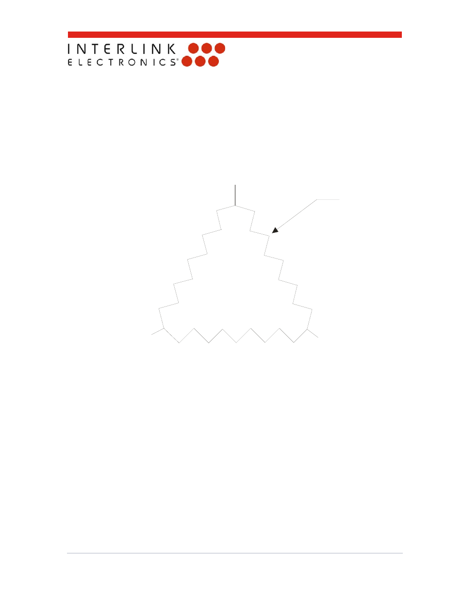
At any one time, the two drivelines furthest from the point of touch are being driven.
The Interlink sensor is shown schematically in Fig. 2. The sensor has four connections. Three of
the connections are drivelines for the resistor ring. The fourth line is the sense line.
The algorithm for measuring this sensor is straightforward and can be implemented in any small
microcontroller. Described in Section 5 is an algorithm using one eight-bit ADC and three general-
purpose I/O lines. Instead of an ADC, one could also use an op-amp voltage follower and a slope
converter.
Figure 2: Schematic representation of the Ring Sensor.
Advertising